Skip to content

The Machine · Recipes

Windmill Arpeggio Machine

Design stage

Updated 2026-10-19

A wheel of eight single-string arms turns past a pick. Each arm is one step of a step sequencer you can watch: the wheel's speed is the tempo, and the pick swings clear for a rest.

Loading the model

Drag to turn · scroll to zoom

Printed

3DWhere we started. This is one version: eight arms on a wheel about 93 cm across, a pick on a servo at the bottom, and a felt damper just before it. Press Play to watch it turn at 120 beats a minute, one bar a turn, with the pick swinging clear for the rests. Only the hub cap is printed, and it's drawn in orange; everything else is bought or cut. The strings are drawn thicker than life so they show.

Overview

Cost, roughly
About $440
Printing
About 2 hours
Building
Two weekends
Difficulty
Involved

Anatomy

1
Energy source
A stepper turns the wheel, and its momentum carries each arm past the pick
2
Control
The wheel's speed sets the tempo; a servo swings the pick in to play a step, or clear for a rest
3
Sounding body
Eight guitar strings, one on each arm, each over its own small pickup
4
Reset
None needed. Each arm comes round again, and a felt pad quiets its string just before
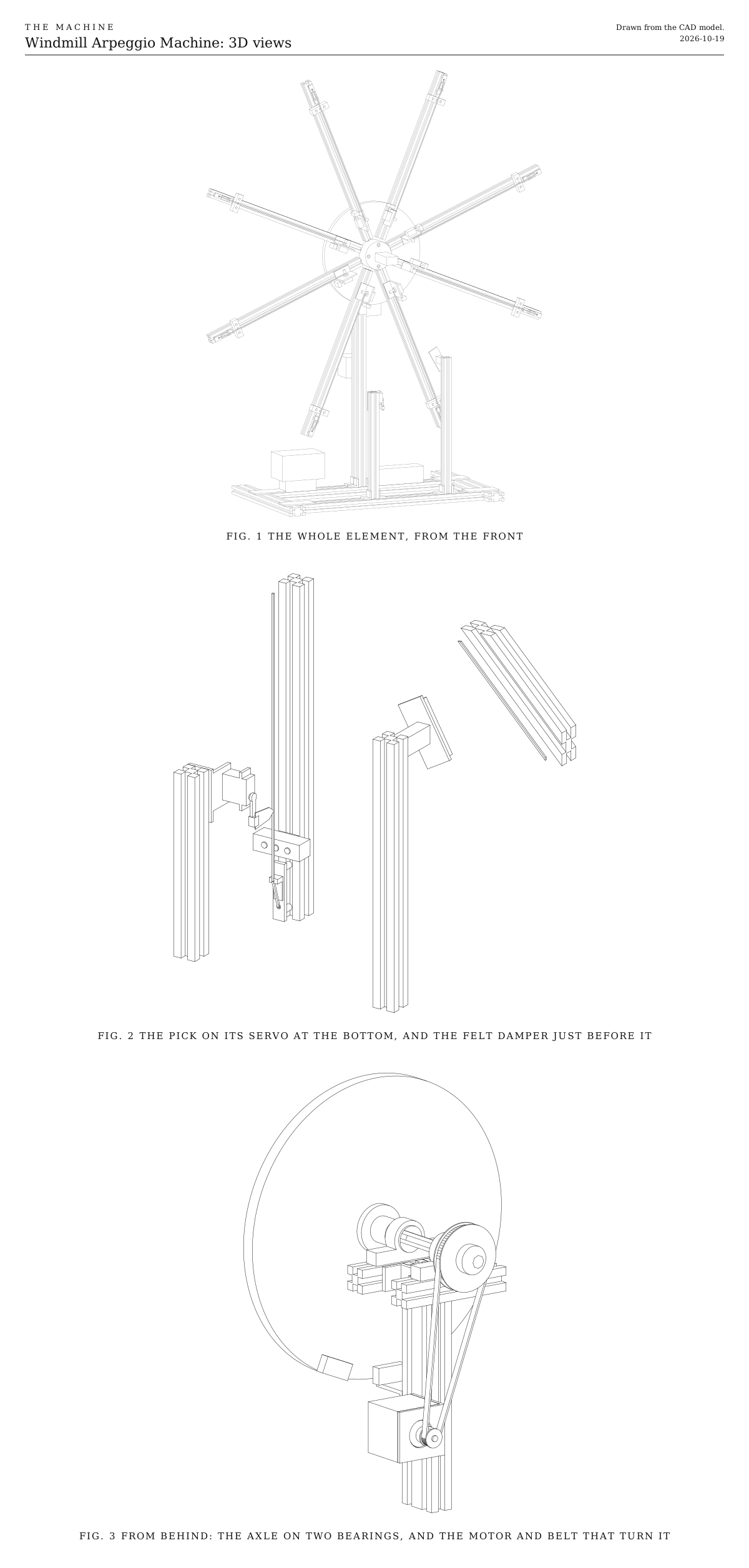
3D views. The whole element from the front, the bottom of the wheel up close where the pick and the felt damper meet the strings, and the drive from behind. Drawn from the CAD model.
Fig. 13D views. The whole element from the front, the bottom of the wheel up close where the pick and the felt damper meet the strings, and the drive from behind. Drawn from the CAD model.
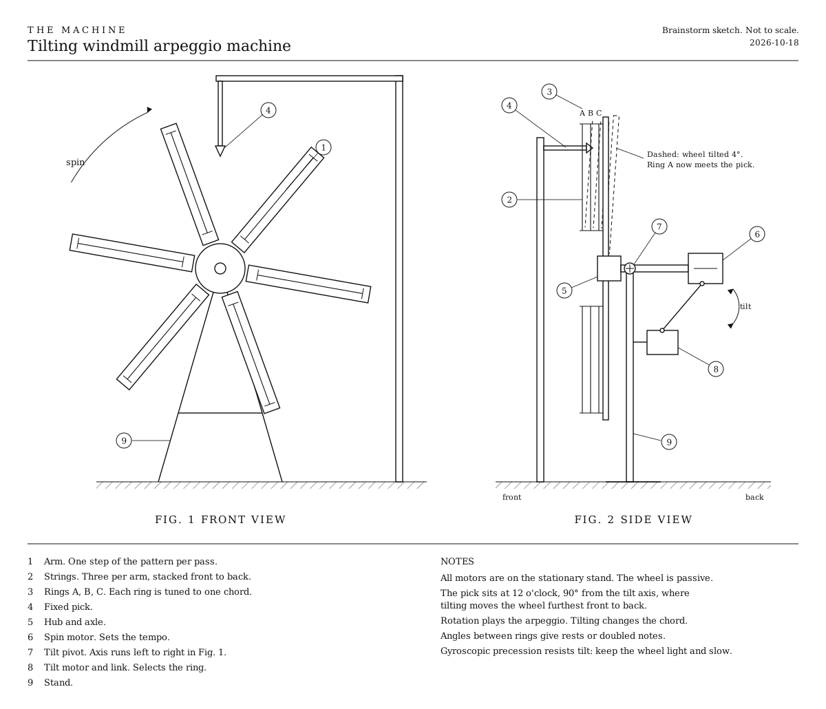
A variation, tilting the wheel to choose the chord. This was the first sketch of this element. Each arm carries three strings, stacked front to back into rings, and tilting the wheel brings a different ring to the pick. See Variations.
Fig. 2A variation, tilting the wheel to choose the chord. This was the first sketch of this element. Each arm carries three strings, stacked front to back into rings, and tilting the wheel brings a different ring to the pick. See Variations.

How it works

  • Eight arms of 2020 V-slot spread out from a plywood hub disc, making a wheel about 93 cm across. Each arm carries one guitar string, 330 mm long, from a tuner near the hub to a bridge at its tip. The tuner, the bridge and the string heights are Lapless Steel’s, so the string elements share their hardware.
  • The wheel turns on a 10 mm axle in two bearings on top of a V-slot post, clockwise as you face it. A stepper turns it through a 4 to 1 toothed belt.
  • One turn is one bar. Each arm is a step. As it passes the bottom, a pick on a servo catches its string and plucks it. At 120 beats a minute in eighth notes, the wheel turns once every two seconds.
  • It keeps time by counting. The ESP32 counts the stepper’s steps, so it always knows which arm is at the pick, and it runs the wheel so each arm arrives on its beat. A reed switch on the post closes once a turn as a magnet behind arm 1 goes by, which keeps the count true.
  • Rests come from the pick. For a rest, the servo swings the pick forward, clear of the strings, and that arm goes by in silence. The wheel never stops, so the pattern can change from one bar to the next.
  • A felt pad just before the pick quiets each string as it comes round. A note rings for nearly a whole turn, and a rest is a true silence.
  • Only sound leaves the wheel. Each arm has a small magnetic pickup. They’re wired together to a jack in the printed hub cap, on the axle’s line, and a wireless guitar sender plugged into it carries the sound to the console. Nothing on the wheel needs power from the stand.
  • An ESP32 on the stand drives the stepper and the servo, and listens to Control like every other element.

The strings

We started with A minor 7, two octaves of it, rising one step at a time round the wheel. Each string is an electric guitar single, on 330 mm between the tuner post and the saddle. The pulls are worked out for nickel-wound and plain steel strings and are close for any brand. Whatever you tune, keep each string between about 60 and 90 N.

Arm Note String Pull
1 E3 .046 wound 81 N
2 A3 .036 wound 90 N
3 C4 .028 wound 78 N
4 E4 .020 plain 75 N
5 G4 .017 plain 77 N
6 A4 .015 plain 75 N
7 C5 .013 plain 80 N
8 E5 .010 plain 75 N

Notes

  • This is a first design, drawn but not yet built. The 3D model and the files show the version we started with. Bought parts vary, so check your tuners, bridges, pickups and pillow blocks against the numbers in the CAD script before drilling.
  • The arms’ tips pass at about 1.5 m/s. Keep hands, hair and cables clear while it turns, and press the stop button before reaching in; the wheel coasts for a few seconds after.
  • Costs in the ingredients are rough estimates for budgeting, not checked prices.
  • Firmware comes with the broadcast control system. For a first test, any stepper and servo example sketch will do.

References

  • A Leslie speaker throws sound around a room from a rotating horn. With acoustic arms, this wheel would move its sound around the room in a similar way.
Parts

Ingredients

KindPartQtySourceEachFile
PrintedHub cap, holds the output jack on the axle's line and covers the pickups' wires where they meet1··STL
FabricatedHub disc, birch plywood, 12 mm thick, 250 mm acrossCut it with a jigsaw, or a router on a circle jig, and drill it with the template in the Files.1·$6.00
FabricatedAluminum angle, 40 x 20 x 3 mm, 40 mm long, one for each tunerDrill one 10 mm hole for the tuner and two 5.5 mm holes for the screws, as on Lapless Steel.8·$1.50
BoughtV-slot extrusion, 20 x 40 mm, two 350 mm feet, two 480 mm crossbars and a 560 mm postMost V-slot sellers cut to length.1·$30.00
BoughtV-slot extrusion, 20 x 20 mm, 425 mm, one for each armYour choice: see How many arms8·$3.50
BoughtV-slot extrusion, 20 x 20 mm, two 100 mm bearing bars, a 280 mm post for the pick and a 350 mm post for the damper1·$6.00
BoughtCorner brackets for 20 mm V-slot12·$0.50
BoughtFlat L joining plates for V-slot, for the base's corners4·$2.00
BoughtM5 screws and T-nuts for V-slotEach arm takes eight, and the stand most of the rest.100·$0.25
BoughtPillow-block bearings, 10 mm bore (KP000)2·$4.00
BoughtSteel shaft, 10 mm, 150 mm longFile a small flat where each set screw bears.1·$5.00
BoughtRigid flange coupling, 10 mm boreIt holds the hub disc on the axle, with four M4 bolts through the disc.1·$6.00
BoughtM4 bolts and nuts, four 55 mm for the hub cap and four 25 mm for the coupling8·$0.20
BoughtGT2 pulley, 80 teeth, 10 mm bore, for 6 mm belt1·$8.00
BoughtGT2 pulley, 20 teeth, 5 mm bore, for 6 mm belt1·$2.00
BoughtGT2 closed belt loop, 6 mm wide, 400 mmWith these two pulleys, it puts the motor's shaft about 149 mm from the axle.1·$3.00
BoughtNEMA 17 stepper motor, 40 mm body, and a steel L-bracket1·$16.00
BoughtSealed guitar tuners for a 10 mm hole, pack of 6 (3 left, 3 right)They're the same ones as Lapless Steel. Eight are used, and either hand works.2·$9.00
BoughtOne-piece single-string guitar bridges, pack of 6They're the same ones as Lapless Steel. The string comes up through the bridge from underneath.2·$22.00
BoughtM3 standoffs, 10 to 12 mm, with M3 screws and T-nuts, two under each bridge16·$0.50
BoughtA small washer with a hole of about 2 mm, under each string's ball end8·$0.10
BoughtElectric guitar strings, singles, .046, .036 and .028 wound, .020, .017, .015, .013 and .010 plainYour choice: see The notesOne for each arm. The table under How It Works gives each one's note and pull.8·$2.00
BoughtSmall single-coil pickups, the kind sold for cigar-box guitars, about 45 x 14 mmYour choice: see Hearing itEach sits on a foam pad on its arm, its middle pole under the string, with a cable tie round the arm in case the foam lets go.8·$8.00
BoughtDouble-sided foam pads and cable ties1·$3.00
BoughtMono jack, 6.35 mm, and thin two-core wireThis is the wheel's one output. Each pickup's wires run along its arm's side slot to the hub cap.1·$4.00
BoughtSlot cover strip for V-slot, to hold wires in the slots1·$4.00
BoughtWireless guitar system, a sender and a receiverYour choice: see Getting the sound off the wheelThe sender plugs into the hub cap's jack; the receiver goes to the console. Pick one whose sender plugs in straight, along its own length.1·$35.00
BoughtMG90S micro servo, metal gears1·$5.00
BoughtAluminum bracket for micro servos1·$4.00
BoughtThick felt, a strip 50 x 20 mm, and a small aluminum angle to hold itYour choice: see How long each note rings1·$4.00
BoughtMagnetic door contact, a reed switch and its magnet, and a small L-bracketThis is the home sensor. It closes once a turn as the magnet behind arm 1 passes, so the ESP32 always knows where the wheel is.1·$3.00
BoughtESP32 development board1·$6.00
BoughtTMC2209 stepper driverIt's quiet, so the motor doesn't whine over the strings.1·$6.00
Bought5 V buck converter, 3 AIt powers the ESP32 and the servo.1·$3.00
BoughtBattery adapter for the shared power-tool platformThe stepper driver runs from the battery, through the fuse, the stop button and the relay.1·$15.00
BoughtThe listener parts every element carries, as on the Control pageA blade fuse holder and 2 A fuse, a latching stop button with a spare contact, the status light, the number switches and their resistors. The stop switch under Choices has a plain two-pole switch in place of the stop button.1Link$12.00
BoughtMomentary push button, normally open, for the test buttonA short press plays each note once, and a long press relearns what the element can by itself. Any small panel button that closes while it's pressed will do.1·$1.00
BoughtRelay module, 5 V, high-level trigger, contacts rated 10 AIt switches the motor's power.1·$2.00
BoughtResistor, 10 kΩIt holds the relay off while the ESP32 starts.1·$0.10
BoughtElectrolytic capacitor, 100 µF, 35 VIt sits across the driver's motor supply, to soak up the spikes the motor sends back.1·$1.00
BoughtSmall project box, about 120 x 40 x 40 mm, for the electronicsYour choice: see The electronics1·$6.00
SalvagedA guitar pick, medium, and a mini binder clip to hold it on the servo hornYour choice: see The pick1··
Total$435.50

Tools

  • 3D printer, PETG or PLA, for the hub cap
  • Jigsaw, or a router with a circle jig, for the hub disc
  • Drill, with 10, 5.5, 4.5 and 2 mm bits; a drill press helps with the disc
  • Hex keys, 2.5, 3 and 4 mm
  • Small screwdriver
  • Soldering iron, for the pickups and the jack
  • Multimeter, to set the converter and check the home sensor
  • A tuner, clip-on or a pedal on the wireless receiver
  • An amp, or the console, to listen

Choices

Decisions that are yours to make. Where we started is the version in the 3D model and the ingredients: a starting point, not the right answer.

How many arms

How many steps does one turn hold?

Four

SoundA bar of quarter notes, or a short riff

Light, and quick to build

EightWhere we started

SoundA bar of eighth notes. At 120 beats a minute the wheel turns at 30 RPM.

Room for a chord across two octaves, and the tuners still fit near the hub

Twelve

SoundTriplets, or a bar of 12/8

The tuners crowd near the hub, so they move out to the tips and the bridges come in

Sixteen

SoundA bar of sixteenth notes, the classic step sequencer

The tuners go to the tips, and the wheel is twice as heavy for the motor to turn

The 3D model and the hub template are drawn for eight. ARMS at the top of the CAD script redraws both for another number.

The notes

What is each arm tuned to?

One chord across two octavesWhere we started

SoundEvery turn is an arpeggio, and any pattern of rests still sounds like music. We started with A minor 7, from E3 up to E5.

A new chord means retuning every string

A pentatonic scale

SoundMelodies rather than chords, and no two notes clash

The rests choose the tune, so the patterns from Control matter more

A drone and its octaves

SoundA hypnotic pulse that the rests carve into rhythm

The easiest to tune, with fewer kinds of string

The table under How It Works gives a string and a pull for each note of the chord we started with.

Retuning

How does a string change its note?

Guitar tuners, by handWhere we started

SoundExact pitch

About a minute a string, with the wheel stopped. They're the same sealed tuners as Lapless Steel.

A sliding saddle on each arm

SoundA chord change in seconds, a little less exact

A second saddle rides in the arm's front slot on a thumb screw, with a mark for each note, like the bridges of a koto. It needs a small holder, made or printed, that isn't drawn yet.

A motor on each arm

SoundNotes that change while it plays, and a glide when a string retunes while it rings

A fourth to a fifth of range per string. It needs a battery, an ESP32 and the motors' drivers riding on the hub. See Variations.

Rests

How does a step stay silent?

The pick on a servoWhere we started

SoundAny step can rest on any turn, so the pattern changes while it plays

One small servo, and the patterns come from Control. The wheel never has to stop.

A fixed pick

SoundEvery arm plays every turn, a steady arpeggio

The simplest build, but the only rest is stopping the wheel.

Hinged arms

SoundRests you set before a piece, and can see from across the room

A folded arm misses the pick, like a missing pin on a music box drum. Each arm needs a hinge that latches both ways.

The pick

What catches each string?

Medium guitar pickWhere we started

SoundA bright, clear attack

Cheap, and wears slowly

Thin pick

SoundLighter, with more snap and less volume

Easier on the motor

Felt or leather pick

SoundA soft, round attack, like a thumb

Quieter, and needs a deeper catch

The pick on its servo is the Motor Pick's servo flick, run from the wheel's own ESP32. The Motor Pick's wheel of picks, with its own ESP32 on its own number, can stand in its place, holding a pick in the strings' path for each step that plays and parking for a rest.

How long each note rings

Where does the felt damper sit?

Just before the pickWhere we started

SoundEach note rings for nearly a whole turn, then stops just before its arm comes round again, so a rest is a true silence

A strip of felt on a small post from the base

A quarter turn after the pick

SoundShort, plucky notes, like a sequencer's gate turned down

The felt moves round to nine o'clock, on a taller post on the left

No damper

SoundEvery string rings on into the next turn, a harp-like wash

The simplest, but a rest only lets the last note keep ringing

Where the felt touches sets the note length, so moving it does what a sequencer's gate knob does.

The drive

What turns the wheel, and how does it keep time?

Stepper and beltWhere we started

SoundIt stays locked to the beat, because the ESP32 counts steps and always knows which arm is at the pick.

It whines faintly. The 4 to 1 belt gives a small motor the strength to turn the wheel.

DC gearmotor with an encoder

SoundSmoother and quieter

It drifts unless the firmware keeps correcting its speed, and it needs a different motor driver.

Free-spinning

SoundNot locked to anything, so the tempo floats

You push it by hand, or a fan blows on the arms like wind on a windmill. It suits an ambient piece.

Hearing it

How does the sound get out?

A magnetic pickup on each armWhere we started

SoundThe clean electric guitar tone of Lapless Steel

About $8 each. They hear the strings and ignore the motor and the belt.

A piezo under each bridge

SoundBrighter and more acoustic, a little thin

About $1 each, but they hear the stepper and the belt through the axle

Acoustic arms

SoundEach arm is a small resonator box. As the boxes sweep round, the sound sweeps round the room, like a Leslie speaker.

Quieter, and heavier to turn. You hear it in the room or through a microphone, and nothing crosses onto the wheel.

Getting the sound off the wheel

How does the pickups' sound cross from the turning wheel to the stand?

A wireless guitar senderWhere we started

SoundClean, with nothing to wear out

It plugs into the jack in the hub cap, on the axle's line, so it doesn't unbalance the wheel. It has its own small battery to charge.

A slip ring

SoundClean when new, but its contacts can crackle as they wear

No battery on the wheel. A through-hole slip ring behind the hub costs about $30 to $50, and its outer half needs a bracket to the stand.

The stop switch

What cuts the motor's power at the element?

Latching emergency-stop button, with a spare contactWhere we started

The red mushroom head anyone nearby knows to hit. It stays down until it's twisted to release, so the element can't start again by accident. Its main contact cuts the power and its spare contact tells the ESP32. About $8.

Two-pole power switch, a rocker or a toggle

Smaller, plainer and cheaper, about $2. One pole cuts the power and the other tells the ESP32, so it does the same job. It doesn't read as a stop to someone who doesn't know the Machine, and it switches back on as easily as off. Rate its contacts above what the element draws, as the button's are.

Keep the second pole either way. The ESP32 knows where the wheel is only by counting the steps it sends, so the second pole is how it learns the power was cut, and finds arm 1's magnet again before it moves. Without it, a wheel turned by hand while it was off would play each step on the wrong string. Either way the relay stays, since it's how a stop from the Bridge reaches the element when no one is at it. A two-pole switch wires as the button does: one pole in place of the main contact, from 11 to 12, and the other in place of the spare contact, from 13 to 14.

Print

Material
PETG
Layers
0.2 mm
Walls
4
Infill
30%

There's one printed part, and it prints without supports. PETG copes with a warm stage and a turning wheel; PLA is fine for a first try.

The printed parts

  • Hub cap, holds the output jack on the axle's line and covers the pickups' wires where they meet

    Which way up
    Front face down, so the open side faces up
    Supports
    None
    Time
    About 2 hours

    The jack's 3/8 inch bushing goes through the hole in its front and is held by its nut. Each pickup's wires come in through the notch in the rim under that arm. Four M4 bolts hold it through the disc.

    STL ↓

Assembly

  1. 1

    Build the base. Lay the two 350 mm feet front to back, 560 mm apart outside to outside, and join them with the two 480 mm crossbars, one 30 mm in from the feet's front ends and one 210 mm in, with a flat L plate across each corner.

    CheckIt sits flat on the floor without rocking.

  2. 2

    Stand the 560 mm post on the middle of the back crossbar, its narrow faces to the front and back, with two corner brackets on each side.

    CheckIt's upright from the front and from the side.

  3. 3

    Bolt the two 100 mm bearing bars across the top of the post, one against its front face and one against its back, flush with its top, with a corner bracket in each corner between bar and post.

    CheckBoth bars' tops are level with the top of the post.

  4. 4

    Set a pillow block on each bar, its two bolts in the bar's top slot, and leave them loose. Slide the axle through both, so about 44 mm sticks out in front, then tighten the blocks and their set screws.

    TrickyThe two blocks must line up exactly, or the axle binds and the motor has to fight it. Tighten them with the axle in place, turning it as you go.

    CheckThe axle turns freely by hand, with no tight spot anywhere in the turn.

  5. 5

    Fit the 80-tooth pulley on the axle just behind the back block, and tighten its set screws on the flats.

  6. 6

    Bolt the motor to its L-bracket with the 20-tooth pulley on its shaft, and bolt the bracket to the post's right side face, in its back slot, below the bearings, the shaft pointing back and the two pulleys in line.

  7. 7

    Fit the belt round both pulleys, slide the motor down its slot until the belt is snug, and tighten the bracket.

    TrickyHold a straight edge across both pulleys' faces. If they're out of line, the belt walks off one of them.

    CheckPressed in the middle, the belt gives a few millimeters. Turn the axle by hand, and the motor turns four times as fast.

  8. 8

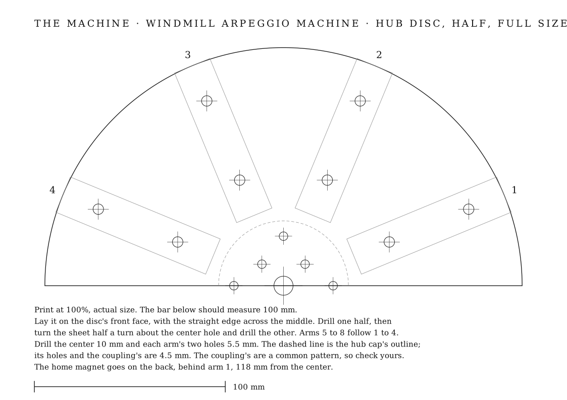
    Cut the hub disc, and drill it with the paper template from the Files, the center, two holes for each arm, and the holes for the hub cap and the coupling.

    TrickyThe center hole has to be truly central and square to the face. If it isn't, the strings rise and fall as the wheel turns, and the pick catches some harder than others.

  9. 9

    Bolt the flange coupling to the middle of the disc's back with four M4 bolts, and glue the door contact's magnet on the back, behind arm 1, 118 mm from the center.

  10. 10

    Make up the first arm. Bolt a drilled aluminum angle and its tuner into the front slot near one end of a 425 mm length of 2020, with the tuner's post 55 mm from that end. Stand the bridge on its two standoffs at the other end, with its saddle 40 mm from that end.

    CheckPost to saddle, the string's length is about 330 mm.

  11. 11

    Stick the pickup to the arm on its foam pad, 27 mm in from the saddle, its middle pole where the string will run, and tie it on with a cable tie. Lay its wires in the arm's side slot, out to the inner end.

  12. 12

    Bolt the arm to the disc's front face with two M5 screws from the back into T-nuts in its back slot, and bolt a bare length of 2020 opposite it as a counterweight.

    CheckThe wheel stays wherever you leave it. If it always swings back to the same place, that side is heavy.

  13. 13

    Slide the disc onto the front of the axle until the axle is flush with its front face, and tighten the coupling's set screws.

    CheckSpin it by hand. The arm's tip moves no more than a millimeter or two toward or away from you.

  14. 14

    String the arm. Thread the small washer onto the string, feed it up through the bridge from underneath so the washer and the ball end sit under it, then over the saddle and onto the tuner post. Wind it so the string leaves from the top of the post, and tune it to its note: E3 for arm 1.

    CheckPlucked by hand, it rings clearly, with no buzz.

  15. 15

    Stand the pick's post on the front crossbar, 40 mm left of the middle. Bolt the servo's bracket to its back face and the servo into it, shaft pointing right, and clip the pick to the tip of the horn so it points back toward the wheel.

  16. 16

    Center the servo with the horn pointing straight down, then set how far the pick sticks out of its clip, so it reaches 1 to 2 mm past the string.

    TrickyToo deep, and the pick snags and the motor strains; too shallow, and strings get missed. Every string has to cross the pick at the same height, so set each one with its bridge saddle.

    CheckTurn the wheel slowly by hand. The pick catches the string, bends, and lets go with a clean pluck.

  17. 17

    Stand the damper's post on the front crossbar, 150 mm right of the middle, and bolt its felt on its small angle, so the felt just touches each string as it passes.

    TrickyThe felt should only kiss the strings. Pressed harder, it drags on the wheel and can pull strings out of tune.

    CheckPluck the string, turn the wheel slowly past the felt, and the ringing stops.

  18. 18

    Bolt the door contact on its small L-bracket on the post's front face, 118 mm below the axle, facing the disc's back, about 5 mm from the magnet's path.

    CheckWith a multimeter across its two wires, it closes as arm 1 passes the pick.

  19. 19

    Add the other arms in opposite pairs, so the wheel stays balanced. Arm 5 replaces the counterweight, then 3 and 7, then 2 and 6, and 4 and 8. String and tune each as it goes on.

  20. 20

    Solder the pickups at the hub. Every hot wire goes to the jack's tip, and every ground wire and a wire from each bridge's screw to its sleeve. Fit the jack in the hub cap, and bolt the cap over the joints.

    CheckPlugged into an amp, every string comes through.

  21. 21

    Mount the electronics box and the battery adapter on the back crossbar, either side of the post, and the stop button on the post's back face, and wire them as the Wiring tab shows.

    TrickyKeep every wire clear of the wheel. Run them down the post's back slot and along the base, behind the wheel.

  22. 22

    Before any code, turn the wheel by hand with the motor's power off, pluck through a whole turn, and listen through the wireless receiver.

Wiring

The fuse comes first, right after the battery. The ESP32 and the servo run from the 5 V converter. The motor's power goes through the stop button and then the relay, so either one cuts it. On the wheel, the pickups are wired on their own, all together to one jack in the hub cap, and the wireless sender carries their sound to the console. Nothing else crosses onto the wheel. The status light, the number switches and the battery reading are wired the same way on every element, so they're on the Control page, not here.

Wiring · Windmill Arpeggio Machine
PowerSignalMotorGround, all joinedPins drawn faint are left empty.

Wire list

  1. Battery adapter, +

    Fuse, 2 A, in

    PowerRed, 16 AWG

    Keep it as short as the adapter allows. Nothing connects ahead of the fuse.

  2. Fuse, 2 A, out

    5 V converter, IN+

    PowerRed, 22 AWG

  3. Fuse, 2 A, out

    Stop button, 11

    PowerRed, 18 AWG

  4. Stop button, 12

    Relay module, COM

    PowerRed, 18 AWG

    The stop button's main contact opens when pressed, cutting the motor's power itself, so a program that hangs can't ignore it.

  5. Relay module, NO

    TMC2209 driver, VM

    PowerRed, 18 AWG

  6. Capacitor, 100 µF, +

    TMC2209 driver, VM

    PowerThe capacitor's own leg

    Solder its legs straight onto the driver's VM and GND pins. The stripe on its side marks the − leg.

  7. 5 V converter, OUT+

    ESP32 board, 5V

    PowerRed, 22 AWG

    Connect it only once the converter is set to 5 V.

  8. 5 V converter, OUT+

    Relay module, VCC

    PowerRed, 22 AWG

  9. 5 V converter, OUT+

    MG90S servo, +

    PowerThe servo's red lead, extended in red 22 AWG

    It comes straight from the converter, not from the ESP32's 5V pin. The servo's pull when it swings would reset the board.

  10. ESP32 board, 3V3

    TMC2209 driver, VDD

    PowerRed, 22 AWG

    The driver's logic runs at the ESP32's 3.3 V, so its signals match.

  11. Battery adapter, −

    5 V converter, IN−

    GroundBlack, 22 AWG

  12. Battery adapter, −

    TMC2209 driver, GND

    GroundBlack, 18 AWG

    This is the motor's return. Use the driver's GND pin next to VM.

  13. Capacitor, 100 µF, −

    TMC2209 driver, GND

    GroundThe capacitor's own leg

  14. 5 V converter, OUT−

    ESP32 board, GND

    GroundBlack, 22 AWG

  15. 5 V converter, OUT−

    MG90S servo, −

    GroundThe servo's brown lead, extended in black 22 AWG

  16. ESP32 board, GND

    TMC2209 driver, GND

    GroundBlack, 22 AWG

    Use the driver's other GND pin, next to VDD.

  17. Relay module, GND

    ESP32 board, GND

    GroundBlack, 22 AWG

  18. Resistor, 10 kΩ, 2

    ESP32 board, GND

    GroundThe resistor's own leg

  19. Home sensor (door contact), 2

    ESP32 board, GND

    GroundThe door contact's other wire, extended in black 22 AWG

  20. Stop button, 14

    ESP32 board, GND

    GroundBlack, 22 AWG

  21. Test button, 2

    ESP32 board, GND

    GroundBlack, 22 AWG

  22. ESP32 board, GPIO 25

    TMC2209 driver, STEP

    SignalAny color, 22 AWG

  23. ESP32 board, GPIO 26

    TMC2209 driver, DIR

    SignalAny color, 22 AWG

  24. ESP32 board, GPIO 27

    TMC2209 driver, EN

    SignalAny color, 22 AWG

    Low turns the motor on. While the element waits, the ESP32 holds it high, so the motor rests silently.

  25. ESP32 board, GPIO 33

    Relay module, IN

    SignalAny color, 22 AWG

  26. Resistor, 10 kΩ, 1

    Relay module, IN

    SignalThe resistor's own leg

    It holds the relay off while the ESP32 starts, when its pins float.

  27. ESP32 board, GPIO 18

    MG90S servo, SIG

    SignalThe servo's orange lead, extended in any color, 22 AWG

  28. Home sensor (door contact), 1

    ESP32 board, GPIO 32

    SignalOne of the door contact's wires, extended in any color, 22 AWG

    The ESP32's own pull-up holds the pin high; the contact pulls it low once a turn, as the magnet behind arm 1 passes.

  29. Stop button, 13

    ESP32 board, GPIO 13

    SignalAny color, 22 AWG

    This is the stop button's spare contact, so the ESP32 knows it's been pressed.

  30. Test button, 1

    ESP32 board, GPIO 15

    SignalAny color, 22 AWG

    The test button. The ESP32's own pull-up holds the pin high until it's pressed. The board reads GPIO 15 as it starts, but only to choose whether to print, so holding the button then does no harm.

  31. TMC2209 driver, 1A

    Stepper motor, A1

    MotorThe motor's own cable

    1A and 1B go to one coil, 2A and 2B to the other.

  32. TMC2209 driver, 1B

    Stepper motor, A2

    MotorThe motor's own cable

  33. TMC2209 driver, 2A

    Stepper motor, B1

    MotorThe motor's own cable

  34. TMC2209 driver, 2B

    Stepper motor, B2

    MotorThe motor's own cable

  35. Pickups, all eight, hot

    Jack in the hub cap, tip

    SignalThin two-core wire, one core from each pickup, along its arm's side slot

    Every pickup's hot lead joins at the jack's tip, inside the hub cap. On most small single coils the white or red lead is hot. Check yours.

  36. Pickups, all eight, ground

    Jack in the hub cap, sleeve

    SignalThin two-core wire, the other core

  37. Strings and bridges, all eight, bridge

    Jack in the hub cap, sleeve

    SignalAny color, 24 AWG, from one of each bridge's screws

    It grounds the strings, which cuts hum when a hand comes near.

Get these right

Set the converter first
Most 5 V converters come set higher. Turn its screw with the battery in and a multimeter on its output until it reads 5.0 V, and only then connect the ESP32 and the servo. More than about 6 V destroys the board.
The wheel coasts
Pressing the stop button cuts the motor's power at once, and the wheel then coasts to a stop over a few seconds. Wait until it has stopped before reaching in. In normal use, the ESP32 slows it down smoothly first.
The servo isn't behind the stop button
Only the motor's power goes through the stop button and the relay. When the button is pressed, the ESP32 stops sending the servo pulses; a hung program could still twitch it, but it only moves the pick.
The home sensor needs no power
A door contact is a reed switch with two wires, closed while its magnet is near. If the wheel turns a whole turn without it closing, the ESP32 stops the wheel, because the wire is loose or the magnet has come off.
Finding the motor's coils
Motor wire colors vary by maker. Touch two wires together and turn the shaft by hand; if it suddenly turns stiffly, those two are one coil. If the wheel turns the wrong way, swap the two wires of one coil.
Never unplug the motor with power on
Pulling the motor's plug while the driver has power can destroy the driver. Switch off, or press the stop button, first.
Charge the sender
The wireless sender runs on its own battery, for a few hours on a charge. Charge it before a show, and switch it off afterwards.

Mounting

Everything fixes to the V-slot with T-nuts and screws, so any part can slide to a new place or come off with a hex key. The wheel turns on an axle in two bearings, in front of the post, and everything wired on the stand sits behind it.

The base
Two 2040 feet run front to back, joined by two crossbars with flat L plates on top. It reaches forward under the wheel, past the pick, so the wheel can't tip it over.
The post
It stands upright on the back crossbar, its narrow faces to the front and back, with two corner brackets on each side.
The bearings
Two 100 mm bars of 2020 cross the top of the post, one on its front face and one on its back, each held by a corner bracket on either side. A pillow block sits on each, its two bolts in the bar's top slot.
The wheel
The axle's front end carries the flange coupling, the hub disc, the eight arms and the hub cap. Each arm bolts to the disc's front with two M5 screws from behind, into T-nuts in its back slot. The tuner's angle, the bridge's standoffs and the pickup fix to the arm's front slot.
The motor
It hangs on an L-bracket on the post's right side face, in its back slot, below the bearings. The bracket slides up and down the slot to tension the belt.
The pick
Its servo sits in an aluminum bracket on a short post, upright on the front crossbar just left of the middle. The post stands in front of the wheel, clear of everything that turns.
The damper
Its felt sits on a small aluminum angle at the top of a second post on the front crossbar, to the right. Slide the post along the crossbar to move the felt.
The home sensor
The door contact sits on a small L-bracket on the post's front face, facing the back of the disc. Its magnet is glued to the disc, behind arm 1.
The electronics
They sit in a box on the back crossbar, right of the post, behind the wheel.
The battery
The adapter sits on the back crossbar, left of the post, so the pack slides on and off without reaching near the wheel.
The stop button
It sits in its own housing on the post's back face, at about waist height, where a hand finds it from behind or beside the element without reaching past the wheel.
The wires
They run down the post's back slot and along the base, behind the wheel, held by slot covers. The only wires on the wheel are the pickups', each in its own arm's side slot.

The electronics

Hidden in a box, or on show?

Closed boxWhere we started

A small project box, bought or printed, on the back crossbar. Tidy and protected, but it hides the electronics.

Open plate

The boards on standoffs on a flat plate on the back crossbar, with the wires dressed along the slots. The electronics become part of the look. It wants neat wiring, and nothing guards it from knocks.

DIN rail

A short length of 35 mm DIN rail on T-nuts, with each board in a snap-on holder. It looks like a control panel, and any board comes off with a flick. The holders add a few dollars.

Whichever you pick, keep the stop button on the outside, where anyone can reach it.

Where the pick sits

At the bottom of the wheel, or the top?

Six o'clockWhere we started

On a short post from the base. It's the stiffest and simplest mount, and the damper's post stands beside it.

Twelve o'clock

Hung from a tall arm over the top of the wheel, as in the first sketch. It's the most visible, but it takes about a meter more extrusion and a brace, and the damper moves up with it.

Tuning

Tuning

The test button
A short press plays one turn of the wheel with the pick in, so each arm's string sounds once, then swings the pick clear and slows the wheel to a stop. Hold it for two seconds and it turns slowly until arm 1's magnet closes the reed switch, and counts from there. It works only while the element is resting, with no Bridge in range or with the Bridge holding it silent. While it plays or is stopped, the button does nothing. A stop ends a test at once, and pressing again ends one early.
Some steps louder than others
The quiet ones cross the pick lower. Raise their bridge saddles, or lower the loud ones, until every step speaks alike.
A knock or a stumble at each step
The pick catches too deep. Back it out of its clip a little. If steps are missed instead, set it deeper. Aim for 1 to 2 mm.
Notes a hair behind the beat
The pluck comes a moment after an arm reaches the pick, when the string slips off. The ESP32 holds a small timing offset; nudge it until the wheel's notes land with the other elements'.
The speed surges once a turn
The wheel is out of balance, so the motor strains on one side and coasts on the other. Turn it by hand with the motor off. If it always settles with the same arm down, that side is heavy; tape washers to the arm opposite until it stays wherever you leave it.
A scratch as strings pass the felt, or notes that ring through it
A scratch means the felt presses too hard; ease it back. A note that rings on past it means the felt isn't touching; bring it in.
Strings drifting out of tune
Tune with the wheel stopped, plucking one string at a time into a tuner on the wireless receiver. New strings stretch, so let it turn for a few minutes and tune again.
A hum
Check the wire from the bridges to the jack's sleeve. The pickups don't hear the motor, but they do pick up hum near amplifiers and stage lights.

Variations

A bigger or smaller wheel
Nothing here depends on 93 cm. Longer arms give longer strings, which sit lower, or pull harder for the same note; keep each string between about 60 and 90 N. The post grows with the wheel, so the arms clear the floor.
Tilting the wheel to choose the chord
Each arm carries several strings stacked front to back, forming rings, and each ring is tuned to a chord. A motor tilts the wheel's axle so a different ring passes the pick, and in-between angles give rests or doubled notes. The pick stays at six or twelve o'clock, 90 degrees from the tilt's own axis, where tilting moves the strings furthest. Gyroscopic precession pushes back on the tilt, so keep the wheel light and slow and size the tilt motor for it. Sliding the axle, or moving the pick, chooses rings the same way without that fight, but is less dramatic to watch. The second drawing shows it.
Retuning while it plays
A small motor on each arm pulls its string's end to change its note, by a fourth to a fifth, which suits moving between chords. Retune on the back half of the turn, or while a string still rings for a glide. The motors' drivers, an ESP32 and a battery ride on the hub, and only Control's signal crosses to the wheel, by radio.
More than one pick
A second pick opposite the first plays every step twice a turn. Picks at uneven spacing play the pattern against itself, like a round.
A carousel
Lay the wheel flat on an upright axle and it turns like a carousel, with the pick reaching in from the side. The arms no longer swing up and over, so the balance matters less.
The wheel as the pick
Turn it inside out. The wheel carries picks, and fixed strings stand round it, each plucked as a pick sweeps by.