Skip to content

The Machine · Recipes

Whirling Striker Drum

Design stage

Updated 2026-10-19

Spinners are motors whirling a wooden ball on a short tether. They run at full speed all the time and strike only when moved so the ball's path crosses the drum head.

Loading the model

Drag to turn · scroll to zoom

Printed

3DWhere we started. One version of it: a 16 inch floor tom, two spinners whirling 40 mm felt-covered balls 30 cm from their hubs, on lead-screw slides. Press Play to see it at a third of real speed. The top spinner drops into the drum's path and strikes once, then the bottom one rises and strikes. The ball's recovery after each hit is simulated with guessed figures. The guard panels are left off so you can see in. Printed parts are drawn in orange; everything else is bought.

Overview

Cost, roughly
About $710
Printing
About an hour
Building
Two weekends
Difficulty
Involved

Anatomy

1
Energy source
Geared motors that spin at full speed all the time, each whirling a ball on a line
2
Control
A slide moves a spinner about 6.5 cm toward the drum, so its ball's circle crosses the head
3
Sounding body
A floor tom on its side, its head toward the audience
4
Reset
The slide pulls the spinner back out, and the spin swings the ball back into line
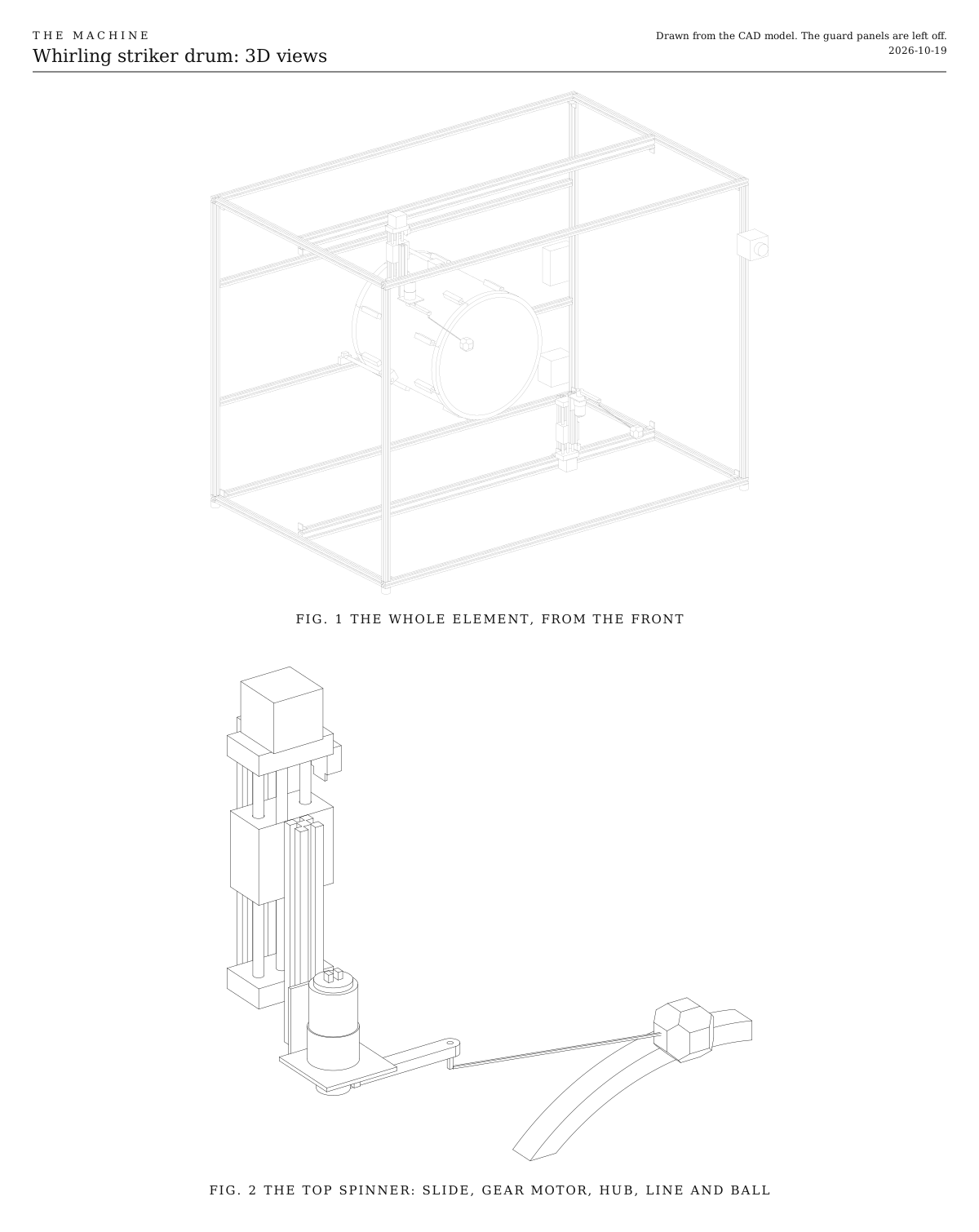
3D views. The whole element from the front with the guard panels left off, and the top spinner up close with its slide, gear motor, hub, line and ball. Drawn from the CAD model.
Fig. 13D views. The whole element from the front with the guard panels left off, and the top spinner up close with its slide, gear motor, hub, line and ball. Drawn from the CAD model.
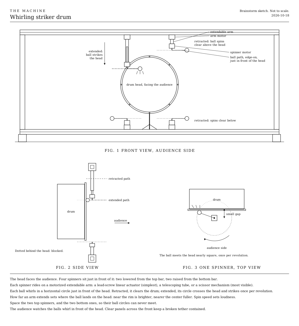
Main version. The first sketch. One drum head facing the audience, with four spinners just in front of it on extendable arms. Retracted, the ball spins clear of the head; extended, it strikes the head.
Fig. 2Main version. The first sketch. One drum head facing the audience, with four spinners just in front of it on extendable arms. Retracted, the ball spins clear of the head; extended, it strikes the head.
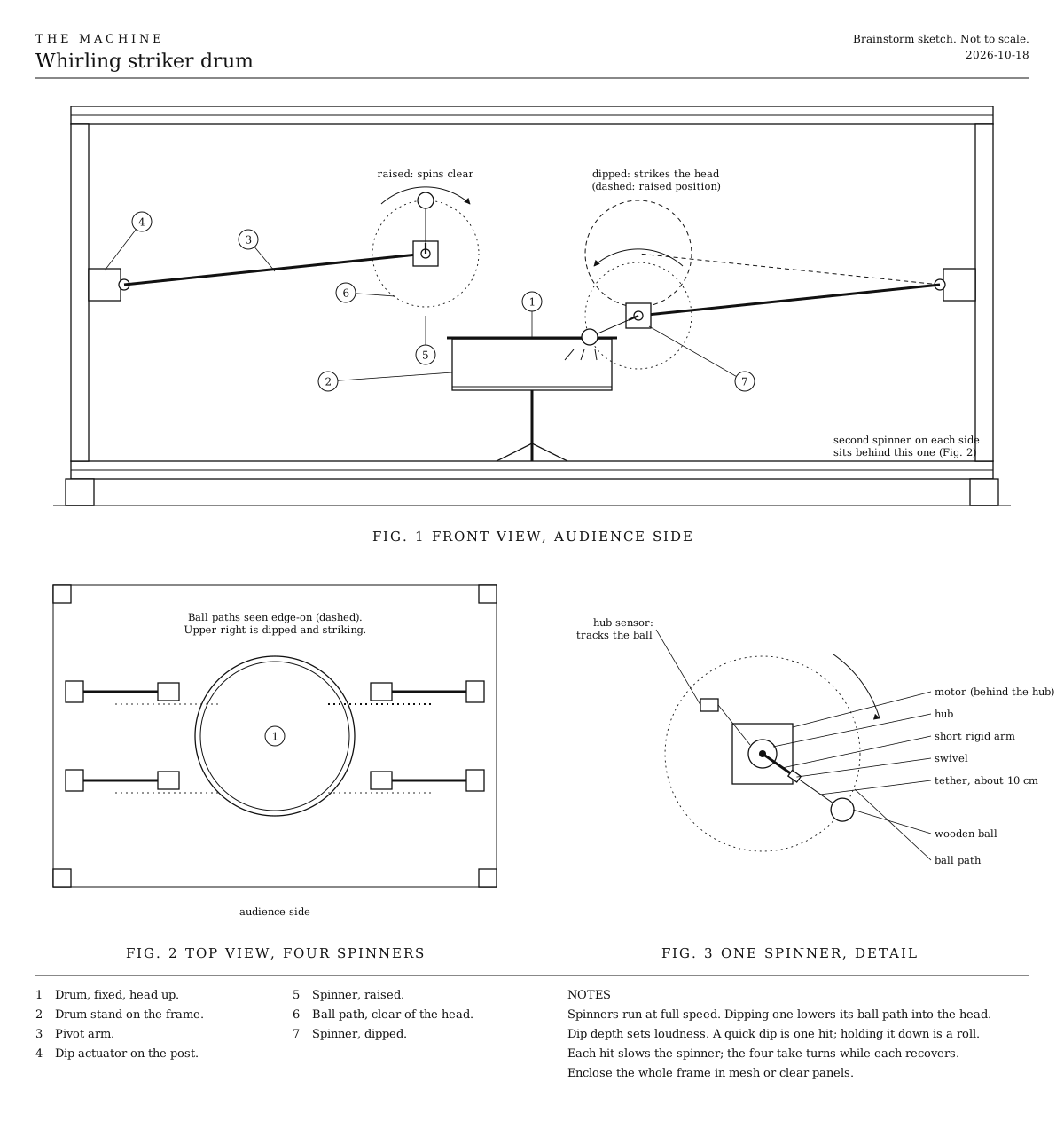
Head up variant. Head up, spinners dip on pivot arms. Raised, the ball spins clear; dipped, it strikes the head.
Fig. 3Head up variant. Head up, spinners dip on pivot arms. Raised, the ball spins clear; dipped, it strikes the head.
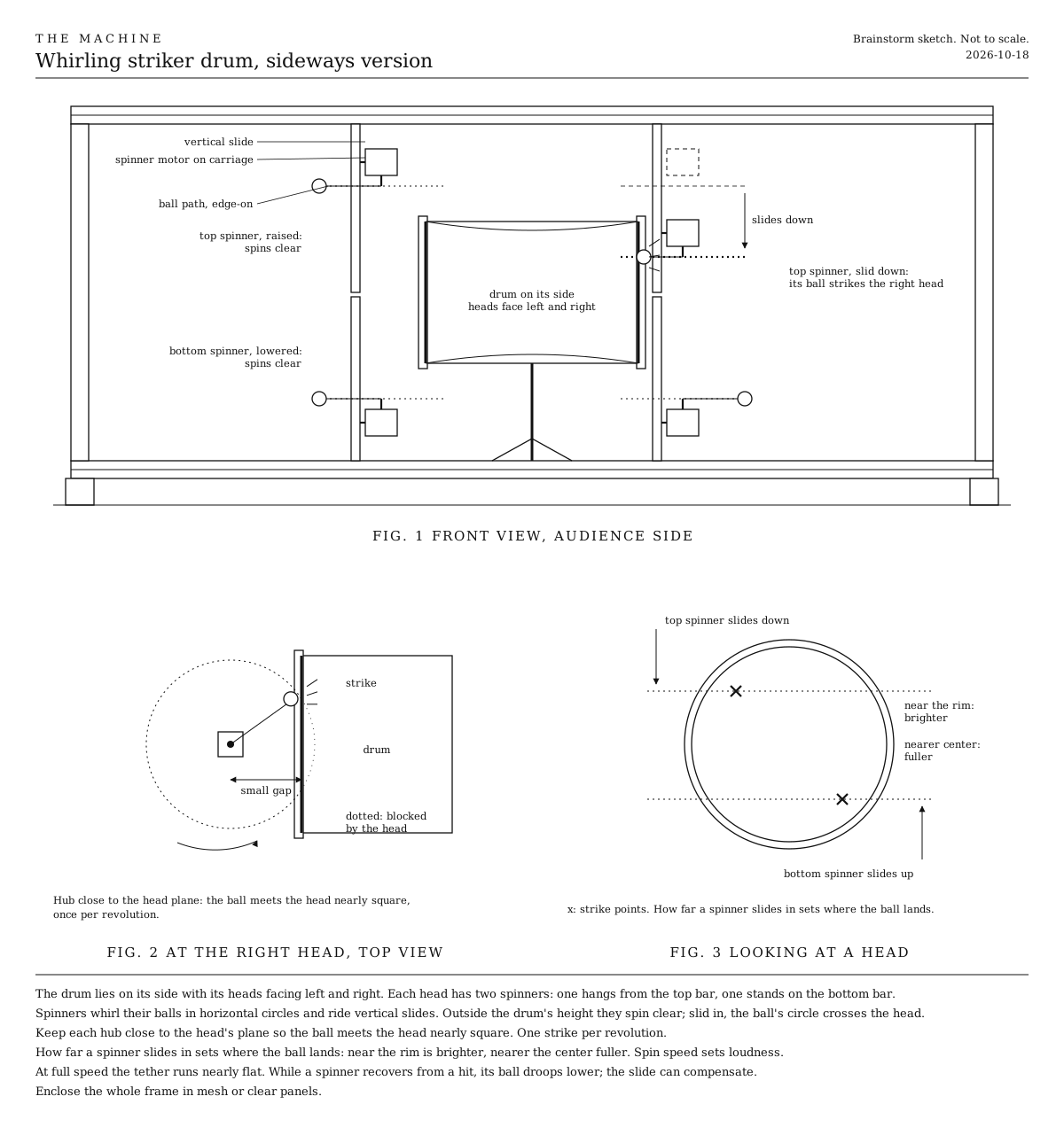
Sideways variant. Heads facing the sides.
Fig. 4Sideways variant. Heads facing the sides.
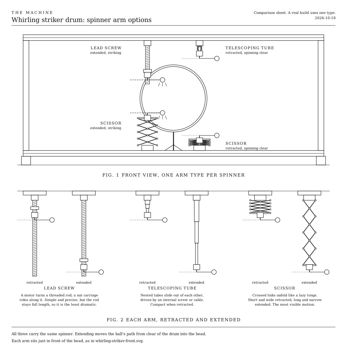
Spinner arm options. Lead-screw linear actuator, telescoping tube, and scissor mechanism compared. A build uses one type.
Fig. 5Spinner arm options. Lead-screw linear actuator, telescoping tube, and scissor mechanism compared. A build uses one type.

How it works

  • A floor tom lies on its side in a box of aluminum extrusion, its head toward the audience. Two spinners sit just in front of the head. One hangs from the top bar on the left, and one stands on the bottom bar on the right.
  • Each spinner whirls a ball all the time. A geared motor turns a hub with a short rigid arm. A stiff line on a swivel runs from the end of the arm to a felt-covered wooden ball, 30 cm from the hub’s axis. At 120 rpm the ball travels at about 3.8 m/s, and the line droops about 12 degrees.
  • Parked, the ball passes clear. Its circle lies just above the drum, or just below it. Half of the circle passes behind the head’s plane, over the shell or beside it.
  • Moved in, it strikes. A lead-screw slide moves the spinner about 6.5 cm toward the drum’s middle. Now the ball’s circle crosses the head’s plane just inside the hoop, and the ball meets the head nearly square, once a turn.
  • One hit at a time. The slide moves in while the ball is out in front, and pulls back out as soon as it strikes. Staying in for several turns gives several hits, but uneven ones, because the ball is still recovering from the last.
  • The hit throws the ball back. It swings back round the end of the hub’s arm, nearly half a turn behind it, and the spin pulls it into line again within three or four turns, if the line calms it. So each spinner wants a few beats between hits, and the spinners take turns.
  • Where it lands sets the tone. Near the rim is brighter; nearer the middle is fuller. Spin speed sets loudness.
  • It plays on the beat. Set the speed to the tempo. At 120 rpm and 120 beats a minute, a turn is a beat, so every hit lands on the grid. A Hall sensor sees a magnet in the hub once a turn, so the program can hold each spinner to the beat and time each move in.
  • Stopping. The stop button cuts all the motors’ power. The hubs stop within a turn and the lines wind round them, which stops the balls quickly. Unwind them before starting again.
  • An ESP32 listens for the wireless signal and drives two stepper drivers for the slides and two motor drivers for the spinners. It runs from the shared power-tool battery.

Safety

  • A whirling ball is the hazard here. If a line breaks, the ball leaves sideways in its plane at about the speed of a firm throw. The guard covers every ball’s path at every slide position, and nothing opens without a tool.
  • Never reach in while anything turns, and wait for the balls to hang still after a stop.
  • Spin up over a few seconds, so the lines straighten out before full speed.
  • Check the crimps and the swivels before every show. Trimmer line tires where it bends at the crimp.
  • In any test with the guard off, wear safety glasses and keep everyone out of the balls’ plane.

Notes

  • This is a first design, drawn but not yet built. Expect one round of fitting.
  • The first sketches hoped for a strike move of 1 to 2 cm. In the model it’s about 6.5 cm, because the ball is 4 cm across and the hoop stands nearly 2 cm proud of the head, and the ball has to clear both. That puts the lead screw near its top speed.
  • The recovery after each hit in the 3D model is simulated, with guesses for how hard the head throws the ball back and how much the line calms it. With those guesses the ball swings back nearly half a turn and settles in three or four turns without touching the drum again. With nothing calming the line it whips right round the end of the arm, and with too much the turning hub drags it back into the head for a second, softer hit. The first test in the Assembly tab shows what really happens.
  • Costs in the parts list are rough estimates for budgeting, not checked prices. They add up the version we started with.
  • There’s no firmware yet. It will listen for Control, the one broadcast signal every element hears.

Parts

Ingredients

KindPartQtySourceEachFile
PrintedHub, grips the gear motor's shaft and carries the line2··STL
BoughtShaft supports to fit the drum's legs (SK12 for 12 mm legs)Your choice: see The drumMost floor tom legs are 10.5 or 12.7 mm across. Measure yours before buying.3·$3.00
BoughtAluminum extrusion, 20 x 20 mm V-slot, 1450 mm, for the front and back of the top and bottom4·$13.00
BoughtAluminum extrusion, 20 x 20 mm V-slot, 880 mm, for the sides of the top and bottom4·$8.00
BoughtAluminum extrusion, 20 x 20 mm V-slot, 1008 mm, for the posts4·$8.00
BoughtAluminum extrusion, 20 x 40 mm V-slot, 1410 mm, for the spinner bars2·$21.00
BoughtAluminum extrusion, 20 x 20 mm V-slot, 1410 mm, for the back bars that hold the drum's legs2·$13.00
BoughtAluminum extrusion, 20 x 20 mm V-slot, 200 mm for the drop posts and 175 mm for the drop arms4·$2.00
BoughtCorner brackets for 20 mm V-slot, with screws and T-nuts36·$1.00
BoughtFeet for 20 mm V-slot, rubber or levelling4·$2.00
BoughtLead-screw slide, 100 mm travel, with its NEMA 17 stepper, T8 screw with an 8 mm leadYour choice: see How a spinner moves inSold for CNC and 3D printer builds. Its end blocks bolt flat to a 20 mm drop post.2·$45.00
BoughtTMC2209 stepper driver2·$6.00
BoughtElectrolytic capacitor, 100 µF, 35 VAcross each stepper driver's motor supply, to soak up the spikes the motor sends back.2·$1.00
BoughtMicro switch with a lever, for each slide's parked end2·$1.00
BoughtGeared DC motor, 37 mm, 24 V, about 200 rpm, with its L-bracketYour choice: see What spins the hubSold as JGB37-520. The bracket bolts to the drop arm with two T-nuts.2·$14.00
BoughtMotor driver board, DRV8871Your choice: see What spins the hubOne for each gear motor. It runs from the battery and takes its speed from the ESP32.2·$5.00
BoughtCeramic capacitor, 0.1 µFAcross each gear motor's two terminals, if it didn't come with one, so the motor's sparks don't upset the radio.2·$0.20
BoughtHall sensor, A3144, the bare three-legged part, and a 6 x 3 mm magnetNot a sensor board with its own pull-up resistor; see the Wiring tab.2·$1.00
BoughtFishing swivel, ball-bearing, with a split ring2·$2.00
BoughtTrimmer line, 2.4 mm round, with two crimp sleevesYour choice: see The lineAbout 25 cm a spinner.1·$8.00
BoughtHardwood ball, 40 mm, drilled throughYour choice: see The ball2·$2.00
BoughtWool felt, 2 to 3 mm, a small sheetYour choice: see The ball1·$5.00
BoughtESP32-S3 development board1·$6.00
BoughtBattery adapter for the shared power-tool platform, and a 5 V buck converterThe motors run from the battery, through the fuse, the stop button and the relay. The ESP32 and the Hall sensors take 5 V.1·$15.00
BoughtThe listener parts every element carries, as on the Control pageA blade fuse holder and a 3 A fuse, a latching stop button with a spare contact, the status light, the number switches and their resistors. The stop switch under Choices has a plain two-pole switch in place of the stop button.1Link$12.00
BoughtMomentary push button, normally open, for the test buttonA short press plays each note once, and a long press relearns what the element can by itself. Any small panel button that closes while it's pressed will do.1·$1.00
BoughtRelay module, 5 V, high-level trigger, contacts rated 10 AThe switch all four motors' power goes through. A relay, not the MOSFET module the Control page also allows, because a MOSFET module switches the ground side, which would leave the stepper drivers grounded only through the ESP32.1·$2.00
BoughtProject box, big enough for four driver boardsYour choice: see The electronics1·$8.00
BoughtWire, 18 and 22 AWG, stranded, and a small terminal block1·$8.00
BoughtClear polycarbonate sheet, 2 mm, cut to the front opening, about 1410 x 1008 mmYour choice: see The guard1·$100.00
BoughtWelded wire mesh, 12 mm, for the sides, the back and the topYour choice: see The guardAbout 4.5 square meters.1·$40.00
BoughtPanel clips for 20 mm V-slotYour choice: see The guard40·$0.50
BoughtM5 screws, T-nuts and washers, and M3 screws and nuts, assortedAn M3 x 8 set screw and nut for each hub.1·$10.00
SalvagedFloor tom, 16 inch, used, with its legsYour choice: see The drumAny make. Its three legs, cut short, are what it hangs from.1·$80.00
Total$714.40

Tools

  • 3D printer, PETG
  • Hex keys, 1.5, 2.5, 3 and 4 mm
  • A drum key, to swap the heads and tune
  • A hacksaw, for the drum's legs
  • Tin snips, for the mesh, and a fine-toothed saw for the polycarbonate
  • A crimping tool or pliers, for the line's sleeves
  • Soldering iron, for the wiring
  • A multimeter, to set the 5 V converter
  • A cordless drill and a phone that films in slow motion, for the first test
  • Safety glasses

Choices

Decisions that are yours to make. Where we started is the version in the 3D model and the ingredients: a starting point, not the right answer.

The drum

What does the ball strike?

Floor tom, 14 or 16 inchWhere we started

SoundA round boom that rings on

Easy to find used. It hangs from its own legs, and its deep shell sits behind the head, out of the balls' way.

Frame drum, 16 to 18 inch

SoundA dry, deep thump that stops short

Light and shallow, and easy to hold with three clamps on its rim. With no shell behind it, the balls can whirl right behind the head.

Bass drum, 18 to 22 inch

SoundThe biggest boom

Heavy, and the frame grows to match.

Snare drum

SoundA sharp crack with the buzz of its wires

Small. A harder ball brings out the crack, and felt mutes it.

Whatever the drum, the struck head faces the audience, and the parked balls pass about a centimeter clear of its hoop.

The ball

What does the line whirl?

Hardwood ball, 40 mm, covered in feltWhere we started

SoundRound, like a soft mallet

About 25 g. The felt spares the head and keeps the click out of each hit.

Bare hardwood ball, 40 mm

SoundBrighter, with a click at the start of each hit

Wears the head, and bounces off harder, so it swings further back after each hit.

Felt ball, 50 mm

SoundLouder and fuller

About twice the weight, which pulls harder on the line and the hub. The parked heights need setting again.

A light ball is the point. Each hit slows only the ball, never the motor.

The line

What does the ball whirl on?

Trimmer line, 2.4 mmWhere we started

SoundSilent, so you hear only the hit

Stiff enough to straighten itself after each hit, like a string trimmer's. It slips out of knots, so crimp it.

Short chain

SoundA small clink on each hit

Heavier. Its links rub against each other, which calms the ball sooner after a hit, and it can't kink.

Hinged rigid link

SoundSilent

A light rod on a pivot with a little friction. It calms the ball fastest and looks like a flail. Too stiff and the ball presses into the head and buzzes instead of bouncing off.

Whatever it's made of, it hangs from a fishing swivel, so it can't twist up.

How far the ball whirls

How far is the middle of the ball from the hub's axis?

30 cm, at 120 rpmWhere we started

SoundHits at about 3.8 m/s, half a second a turn

Each ball's circle is about 65 cm across, so the frame is about 1.45 m wide, 1.1 m tall and 0.9 m deep.

20 cm, at about 150 rpm

SoundSofter, at about 3 m/s

The frame shrinks to about 1.1 m wide, but 0.4 s a turn leaves less time for the move in.

Of the 30 cm, 10 cm is the hub's rigid arm and 20 cm is line. A longer rigid arm swings the ball back into line sooner after a hit; a shorter one looks more like a ball on a string.

How many spinners

How many voices?

TwoWhere we started

SoundTwo voices taking turns, one near the top of the rim and one near the bottom

One hangs from the top bar on the left, and one stands on the bottom bar on the right. The frame has room for two more.

Four, as in the first sketch

SoundFuller patterns, because each spinner can rest a few beats between hits

Twice the motors and drivers. The two at the top must sit far enough apart that their balls' circles never meet, and so must the two at the bottom.

One

SoundOne voice, a hit every two or three beats at most

The cheapest, and a good test rig.

How a spinner moves in

What carries a spinner toward the drum?

Lead-screw slideWhere we started

SoundA soft whirr

Bought with its own stepper motor, and it holds still when the power is cut. The strike move of about 6.5 cm in 0.4 s takes it near its top speed, so buy one with an 8 mm lead, not 2 mm.

Belt slide

SoundA faint hum

Bought too, and about three times faster, which makes deeper single hits possible. It drops when the power is cut, so it suits the bottom bar, where dropping pulls the ball away from the drum.

Scissor arm

SoundA rattle of links

The most visible motion, but a build, not a purchase. Drive it near its folded end with a crank, because scissor lifts you can buy are geared for force and are slow.

Telescoping tube

SoundQuiet

Compact when parked. A build too, driven by a screw or a cable inside.

A build uses one type.

What spins the hub

What turns the hub?

Geared DC motor, 24 V, about 200 rpmWhere we started

SoundA low hum

Its gears shrug off the jolt of every hit. On the 18 to 20 V battery it runs at about 150 rpm, and the program holds it to the beat from the Hall sensor's pulse once a turn.

Stepper motor

SoundA faint whine

Locks to the beat with no tuning, on the same kind of driver as the slide. A hard jolt from a hit can make it skip, so it wants a heavy hub to soak up the jolt.

The stop switch

What cuts the motors' power at the element?

Latching emergency-stop button, with a spare contactWhere we started

The red mushroom head anyone nearby knows to hit. It stays down until it's twisted to release, so the element can't start again by accident. Its main contact cuts the power and its spare contact tells the ESP32. About $8.

Two-pole power switch, a rocker or a toggle

Smaller, plainer and cheaper, about $2. One pole cuts the power and the other tells the ESP32, so it does the same job. It doesn't read as a stop to someone who doesn't know the Machine, and it switches back on as easily as off. Rate its contacts above what the element draws, as the button's are.

Keep the second pole either way. The ESP32 knows where the slides are only by counting the steps it sends, so the second pole is how it learns the power was cut, and finds their home switches again before it moves. Without it, a slide pushed by hand while the power was off could be driven into its end. Either way the relay stays, since it's how a stop from the Bridge reaches the element when no one is at it. A two-pole switch wires as the button does: one pole in place of the main contact, from 11 to 12, and the other in place of the spare contact, from 13 to 14.

Print

Material
PETG
Layers
0.2 mm
Walls
4
Infill
60%

The hub fits a 150 mm bed and prints without supports. PETG takes the jolt of each hit better than PLA, and with four walls the arm is nearly solid.

The printed parts

  • Hub, grips the gear motor's shaft and carries the line× 2

    Which way up
    Flat, with the arm on the bed and the boss standing up
    Supports
    None
    Time
    About 30 minutes each

    The motor's D-shaped shaft slides in, and an M3 set screw locks it on the flat; the nut drops into its slot from the top. The magnet presses into the pocket in the arm with a dab of glue.

    STL ↓

Assembly

  1. 1

    Before buying the rest, try one spinner by hand. Tie 30 cm of trimmer line to a short bolt in a cordless drill's chuck, with a swivel at the top and a felt-covered ball at the bottom. Spin it at a medium speed, hold it so the ball's path just reaches a drum head, and film it in slow motion.

    TrickyThe whole element rests on this test. If the ball whips right round and wraps, try the short chain or the hinged link from the choices before going further. Wear safety glasses, and keep everyone out of the ball's plane.

    CheckAfter each hit, the line swings the ball back into line within a turn or two without wrapping the bolt, and the hit sounds like a soft mallet.

  2. 2

    Build the frame. Join the bottom rectangle, the four posts and the top rectangle with corner brackets, two at every joint, and fit a foot under each corner.

    CheckMeasured corner to corner, the two diagonals of each face match, and the frame doesn't rock on a flat floor.

  3. 3

    Fit the two 20 x 40 spinner bars across the frame between the side bars, with the 40 mm side standing up, one flush with the top and one flush with the bottom. Their front faces sit about 470 mm back from the frame's front. Fit the two back bars between the back posts, but leave them loose for now.

  4. 4

    Get the drum ready. Find which end its leg brackets are nearer, and swap the heads if you need to, so the batter head is on the other end. That end faces the audience. Tune it to a low, round note.

    TrickyThe leg brackets have to end up at the back, out of the balls' reach. On most floor toms they're nearer the top head, so the drum's bottom end faces the audience.

  5. 5

    Hang the drum. Cut its three legs to about 260 mm and fit them through the leg brackets, pointing back. Bolt a shaft support for each onto the back bars, then slide the bars and the drum until its axis is about 500 mm up and centered side to side, with its head about 430 mm behind the frame's front.

    TrickyA strip of rubber inside each shaft support keeps the frame from buzzing along with the drum.

    CheckThe head stands upright and square to the front. Tapped, it rings, and nothing on the frame buzzes.

  6. 6

    Bolt each slide along a 200 mm drop post, with its motor at one end. Hang one post from the top bar, motor up, 340 mm left of the drum's middle as the audience sees it. Stand the other on the bottom bar, motor down, 340 mm right of the middle. Use two corner brackets each.

    CheckTurned by hand at the motor's shaft, each carriage runs end to end without catching.

  7. 7

    Fit a home switch at each slide's far end, away from the drum, where the carriage presses it just before it reaches the end block. The program parks the spinner about 36 mm short of it, which leaves room to lift it further while a ball recovers.

  8. 8

    Print the two hubs. Drop an M3 nut into each one's slot and start the set screw. Find which face of a magnet sets off the Hall sensor, then press the magnet into the hub's pocket with that face out and a dab of glue.

    TrickyThe sensor answers only one pole of the magnet. Test it with the sensor wired up before the glue sets.

  9. 9

    Bolt each gear motor into its L-bracket, and the bracket to the end of a 175 mm drop arm. Bolt the drop arm to the slide's carriage so the motor's shaft points away from the slide, down on the top spinner and up on the bottom one.

    CheckWith the carriage at its home switch, the end of the motor's shaft is clear of the slide's end block, with room for the hub.

  10. 10

    Push a hub onto each shaft, the arm on the side away from the motor, and tighten the set screw onto the flat. Glue the Hall sensor to the bracket, flat face toward the hub, where the magnet passes 3 to 6 mm away.

    CheckTurned by hand, the hub runs flat, and the sensor switches once a turn.

  11. 11

    Make the lines. Crimp trimmer line to each swivel and to a ball, so the middle of the ball is 200 mm from the swivel's eye, 300 mm from the hub's axis. Glue felt over the ball. Hang the swivel's split ring through the eye at the end of the hub's arm.

    TrickyTrimmer line slips out of knots. Crimp it, or melt a bead on the end with a lighter, and pull hard. A ball that comes loose is the main danger here.

    CheckPulled hard by hand, nothing slips.

  12. 12

    Mount the electronics box and the battery adapter on the back right post and the stop button on the front right post, and wire them as the Wiring tab shows. Leave a loop of slack in the wires to each gear motor and Hall sensor, which move with the carriage.

    TrickySet the 5 V converter with a multimeter before connecting the ESP32. Most come set higher, and more than about 6 V destroys the board.

    CheckWith the battery in and no program running, nothing moves, and the ESP32's light is on. Press the stop button, release it, and still nothing moves.

  13. 13

    Fit the guard. Clear polycarbonate goes in the front opening, and wire mesh in the sides, the back and the top, all held by panel clips in the slots.

    CheckPushed hard anywhere, no panel moves, and there's no gap a ball could leave through.

  14. 14

    Load a test program. Until the element's firmware exists, any stepper example for the slides and a PWM example for the gear motors will do. Spin one spinner up slowly to 120 rpm, parked, and watch its ball's circle from the side, through the guard.

    TrickyThe line droops less as it speeds up, so set the parked height at playing speed. At 120 rpm the ball's circle sits about 4 cm below the hub's arm. Move the drop arm along the carriage to raise or lower it.

    CheckAt full speed, the ball's circle passes about a centimeter clear of the hoop.

  15. 15

    Move the spinner in for one strike, starting just after the ball has passed beside the drum, and pull it back out as soon as it hits.

    TrickyThe move is about 6.5 cm and has to fit into about 0.4 s while the ball is out in front. With an 8 mm lead, that's about 1,400 rpm at its fastest, near the top of what a NEMA 17 can do. If it stalls or arrives late, raise the driver's current a little, or see the tuning notes.

    CheckOne clean hit just inside the rim, and the ball back in line within two turns.

Wiring

The fuse comes first, right after the battery. The ESP32 and the Hall sensors run from the 5 V converter. All four motors' power goes through the stop button and then the relay, so either one cuts it: the two slides' stepper drivers and the two gear motors' drivers. The status light, the number switches and the battery reading are wired the same way on every element, so they're on the Control page, not here.

Wiring · Whirling Striker Drum
PowerSignalMotorGround, all joinedPins drawn faint are left empty.

Wire list

  1. Battery adapter, +

    Fuse, 3 A, in

    PowerRed, 16 AWG

    As short as the adapter allows. Nothing connects ahead of the fuse.

  2. Fuse, 3 A, out

    5 V converter, IN+

    PowerRed, 22 AWG

  3. Fuse, 3 A, out

    Stop button, 11

    PowerRed, 18 AWG

  4. Stop button, 12

    Relay module, COM

    PowerRed, 18 AWG

    The stop button's main contact opens when pressed, cutting the motors' power itself, so a program that hangs can't ignore it.

  5. Relay module, NO

    TMC2209, top slide, VM

    PowerRed, 18 AWG

    One wire from the relay to a terminal block, and the four motor supplies from there.

  6. Relay module, NO

    TMC2209, bottom slide, VM

    PowerRed, 18 AWG

  7. Relay module, NO

    DRV8871, top spinner, VM

    PowerRed, 18 AWG

  8. Relay module, NO

    DRV8871, bottom spinner, VM

    PowerRed, 18 AWG

  9. Capacitor, 100 µF, +

    TMC2209, top slide, VM

    PowerThe capacitor's own leg

    Solder its legs straight onto the driver's VM and GND pins. The stripe on its side marks the − leg.

  10. Capacitor, 100 µF, +

    TMC2209, bottom slide, VM

    PowerThe capacitor's own leg

  11. 5 V converter, OUT+

    ESP32-S3 board, 5V

    PowerRed, 22 AWG

    Only once the converter is set to 5 V.

  12. 5 V converter, OUT+

    Relay module, VCC

    PowerRed, 22 AWG

  13. 5 V converter, OUT+

    Hall sensor, top spinner, VCC

    PowerRed, stranded 22 AWG, with a loop of slack

  14. 5 V converter, OUT+

    Hall sensor, bottom spinner, VCC

    PowerRed, stranded 22 AWG, with a loop of slack

  15. ESP32-S3 board, 3V3

    TMC2209, top slide, VDD

    PowerRed, 22 AWG

    The drivers' logic runs at the ESP32's 3.3 V, so their signals match.

  16. ESP32-S3 board, 3V3

    TMC2209, bottom slide, VDD

    PowerRed, 22 AWG

  17. Battery adapter, −

    5 V converter, IN−

    GroundBlack, 22 AWG

  18. Battery adapter, −

    TMC2209, top slide, GND

    GroundBlack, 18 AWG

    The motor's return. Use the driver's GND pin next to VM.

  19. Battery adapter, −

    TMC2209, bottom slide, GND

    GroundBlack, 18 AWG

  20. Battery adapter, −

    DRV8871, top spinner, GND

    GroundBlack, 18 AWG

  21. Battery adapter, −

    DRV8871, bottom spinner, GND

    GroundBlack, 18 AWG

  22. Capacitor, 100 µF, −

    TMC2209, top slide, GND

    GroundThe capacitor's own leg

  23. Capacitor, 100 µF, −

    TMC2209, bottom slide, GND

    GroundThe capacitor's own leg

  24. 5 V converter, OUT−

    ESP32-S3 board, GND

    GroundBlack, 22 AWG

  25. ESP32-S3 board, GND

    TMC2209, top slide, GND

    GroundBlack, 22 AWG

    The driver's other GND pin, next to VDD.

  26. ESP32-S3 board, GND

    TMC2209, bottom slide, GND

    GroundBlack, 22 AWG

  27. ESP32-S3 board, GND

    DRV8871, top spinner, GND

    GroundBlack, 22 AWG

    The ground the speed signals are read against. The board has one GND, shared with the battery's.

  28. ESP32-S3 board, GND

    DRV8871, bottom spinner, GND

    GroundBlack, 22 AWG

  29. Relay module, GND

    ESP32-S3 board, GND

    GroundBlack, 22 AWG

  30. Resistor, 10 kΩ, 2

    ESP32-S3 board, GND

    GroundThe resistor's own leg

  31. Home switch, top slide, COM

    ESP32-S3 board, GND

    GroundBlack, 22 AWG

  32. Home switch, bottom slide, COM

    ESP32-S3 board, GND

    GroundBlack, 22 AWG

  33. Hall sensor, top spinner, GND

    ESP32-S3 board, GND

    GroundBlack, stranded 22 AWG, with a loop of slack

  34. Hall sensor, bottom spinner, GND

    ESP32-S3 board, GND

    GroundBlack, stranded 22 AWG, with a loop of slack

  35. Stop button, 14

    ESP32-S3 board, GND

    GroundBlack, 22 AWG

  36. Test button, 2

    ESP32-S3 board, GND

    GroundBlack, 22 AWG

  37. ESP32-S3 board, GPIO 16

    TMC2209, top slide, STEP

    SignalAny color, 22 AWG

  38. ESP32-S3 board, GPIO 17

    TMC2209, top slide, DIR

    SignalAny color, 22 AWG

  39. ESP32-S3 board, GPIO 18

    TMC2209, top slide, EN

    SignalAny color, 22 AWG

    One pin turns both slides' motors on, low for on. The ESP32 holds it high while the element waits, so the motors don't hum.

  40. ESP32-S3 board, GPIO 18

    TMC2209, bottom slide, EN

    SignalAny color, 22 AWG

  41. ESP32-S3 board, GPIO 41

    TMC2209, bottom slide, STEP

    SignalAny color, 22 AWG

  42. ESP32-S3 board, GPIO 42

    TMC2209, bottom slide, DIR

    SignalAny color, 22 AWG

  43. ESP32-S3 board, GPIO 38

    DRV8871, top spinner, IN1

    SignalAny color, 22 AWG

    The speed, as pulses. The top gear motor turns one way with IN1 pulsed and IN2 low, the other way with them swapped.

  44. ESP32-S3 board, GPIO 39

    DRV8871, top spinner, IN2

    SignalAny color, 22 AWG

  45. ESP32-S3 board, GPIO 47

    DRV8871, bottom spinner, IN1

    SignalAny color, 22 AWG

  46. ESP32-S3 board, GPIO 46

    DRV8871, bottom spinner, IN2

    SignalAny color, 22 AWG

    The board reads GPIO 46 as it starts, and needs it low then. The driver's input holds it low, so it's safe here.

  47. ESP32-S3 board, GPIO 5

    Relay module, IN

    SignalAny color, 22 AWG

  48. Resistor, 10 kΩ, 1

    Relay module, IN

    SignalThe resistor's own leg

    Holds the relay off while the ESP32 starts, when its pins float.

  49. Home switch, top slide, NC

    ESP32-S3 board, GPIO 21

    SignalAny color, 22 AWG

    Each switch's normally closed contact, which opens when pressed. A broken wire then reads as pressed, so the slide stops rather than driving into its end.

  50. Home switch, bottom slide, NC

    ESP32-S3 board, GPIO 2

    SignalAny color, 22 AWG

  51. Hall sensor, top spinner, OUT

    ESP32-S3 board, GPIO 40

    SignalAny color, stranded 22 AWG, with a loop of slack

    The sensor only pulls this pin to ground as the magnet passes. The ESP32's own pull-up holds it at 3.3 V the rest of the time.

  52. Hall sensor, bottom spinner, OUT

    ESP32-S3 board, GPIO 3

    SignalAny color, stranded 22 AWG, with a loop of slack

  53. Stop button, 13

    ESP32-S3 board, GPIO 4

    SignalAny color, 22 AWG

    The stop button's spare contact, so the ESP32 knows it's been pressed.

  54. Test button, 1

    ESP32-S3 board, GPIO 14

    SignalAny color, 22 AWG

    The test button. The ESP32's own pull-up holds the pin high until it's pressed, so nothing else goes on this pin.

  55. TMC2209, top slide, 1A

    Top slide's stepper, A1

    MotorThe motor's own cable

    1A and 1B go to one coil, 2A and 2B to the other.

  56. TMC2209, top slide, 1B

    Top slide's stepper, A2

    MotorThe motor's own cable

  57. TMC2209, top slide, 2A

    Top slide's stepper, B1

    MotorThe motor's own cable

  58. TMC2209, top slide, 2B

    Top slide's stepper, B2

    MotorThe motor's own cable

  59. TMC2209, bottom slide, 1A

    Bottom slide's stepper, A1

    MotorThe motor's own cable

  60. TMC2209, bottom slide, 1B

    Bottom slide's stepper, A2

    MotorThe motor's own cable

  61. TMC2209, bottom slide, 2A

    Bottom slide's stepper, B1

    MotorThe motor's own cable

  62. TMC2209, bottom slide, 2B

    Bottom slide's stepper, B2

    MotorThe motor's own cable

  63. DRV8871, top spinner, OUT1

    Top gear motor, +

    MotorRed, stranded 20 AWG, with a loop of slack

  64. DRV8871, top spinner, OUT2

    Top gear motor, −

    MotorBlack, stranded 20 AWG, with a loop of slack

  65. DRV8871, bottom spinner, OUT1

    Bottom gear motor, +

    MotorRed, stranded 20 AWG, with a loop of slack

  66. DRV8871, bottom spinner, OUT2

    Bottom gear motor, −

    MotorBlack, stranded 20 AWG, with a loop of slack

Get these right

Set the converter first
Most 5 V converters come set higher. Turn its screw with the battery in and a multimeter on its output until it reads 5.0 V, and only then connect the ESP32 and the sensors. More than about 6 V destroys the board.
Use the bare Hall sensor
The A3144 needs 5 V to work, but its output only ever pulls to ground, so it's safe on a 3.3 V pin. A sensor board with its own pull-up resistor would put 5 V on the pin and can destroy it. Use the bare three-legged part, or cut the board's resistor off.
Which way the spinners turn
Seen from above, the top spinner turns anticlockwise and the bottom one clockwise, so each ball meets the head on its way toward the middle. If one turns the wrong way, swap its two motor wires.
Finding a stepper's coils
Motor wire colors vary by maker. Touch two wires together and turn the shaft by hand; if it suddenly turns stiffly, those two are one coil. If a slide runs backwards, swap the two wires of one coil.
Never unplug a motor with power on
Disconnecting a running stepper can destroy its driver. Press the stop button first.
The pins
These leave free the pins the shared listening code uses, 1 and 4 to 15, with the test button on 14. Avoid 0 and 45, which the board reads as it starts, 19 and 20, which carry USB, and 43 and 44, which carry the serial console. The board reads 46 as it starts too, but the bottom spinner's driver holds it low, as the board wants it, so it carries that driver's IN2. If you use others, note them for the firmware.

Mounting

Everything fixes to the frame with M5 screws into T-nuts, so any part can slide to a new place or come off with a hex key. The spinners hang from, or stand on, a 20 x 40 bar that crosses the frame just behind the drum's head. The drum hangs from its own legs at the back, and the guard clips into the frame's openings.

The frame
Corner brackets, two at every joint, with M5 screws into T-nuts.
The spinner bars
A 20 x 40 bar across the top and another across the bottom, between the side bars, with two corner brackets at each end. Their front faces sit about 470 mm back from the frame's front, just behind the drum's head.
The slides
Each bolts along its length to a 200 mm drop post, which hangs from the top bar or stands on the bottom bar on two corner brackets. Slide a post along its bar to change where the ball strikes.
The gear motors
Each sits in its L-bracket at the end of a 175 mm drop arm, which bolts to the slide's carriage with T-nuts. Sliding the drop arm along the carriage sets how high the spinner sits.
The drum
Its three legs, cut short, point back from its leg brackets into shaft supports on two back bars. The drum's own wing bolts grip the legs, so it slides forward and back to set the gap between the head and the spinners.
The electronics
In a box on the back of the back right post, outside the guard.
The battery
The adapter sits on the same post, below the box, so the pack slides on and off from behind.
The stop button
In its own housing on the front of the front right post, outside the guard, where a hand finds it without reaching into the frame.
The guard
Clear polycarbonate in the front opening, and wire mesh in the sides, the back and the top, each held by panel clips in the slots. Nothing opens without a hex key.
The wires
The wires to each gear motor and Hall sensor leave the carriage in a loop of slack, then run along the slots behind clip-in covers to the box.

The guard

What stops a loose ball?

Clear front, mesh elsewhereWhere we started

The audience sees the balls whirl through clear polycarbonate. Mesh on the other four sides costs much less and looks like a cage. Polycarbonate, not acrylic, because acrylic cracks into sharp pieces.

Clear all round

The best view from every side, at roughly twice the cost. It needs more than one sheet, because the top and the back are each about 1.4 m long.

Front panel only, against a wall

The cheapest, but only where nobody can walk behind it or beside it.

A ball that breaks loose leaves sideways, in the plane it was whirling in, so the guard has to cover every ball's path at every slide position.

The electronics

Hidden in a box, or on show?

Closed boxWhere we started

A project box, bought or printed, on the back of a post. Tidy and protected, but it hides the electronics.

Open plate

The boards on standoffs on a flat plate on the post, with the wires dressed along the slots. The electronics become part of the look. It wants neat wiring.

Whichever you pick, keep the stop button on the outside, where anyone can reach it.

Tuning

Tuning

The test button
A short press spins both spinners up, brings each in for one strike in turn, then spins them down. Hold it for two seconds and it homes both slides and finds each spinner's magnet again. It works only while the element is resting, with no Bridge in range or with the Bridge holding it silent. While it plays or is stopped, the button does nothing. A stop ends a test at once, and pressing again ends one early.
A clack instead of a boom
The ball is catching the hoop. Move the spinner in a little further, or park it a little higher so it starts from clear. Or keep it; a rim click is a sound too.
Too bright, or too thin
The ball is landing right at the edge. Move it in further for a fuller sound nearer the middle. Because the ball has to pass the rim on its way in, a longer move plays a quick roll that walks in from the edge rather than one deep hit.
Two hits where you wanted one
The spinner stayed in too long, and the ball came round again while it was still swinging back. Pull it out sooner after the hit.
The ball whips right round and wraps
The hit is throwing it back harder than the line can calm it. Use the short chain or the hinged link, or a longer rigid arm on the hub with less line. On the bottom spinner the motor sits under the hub, so a ball that whips all the way round can catch its line on the motor. Watch that one first.
Hits a little late or early
The spinner's turning has drifted off the beat. The program holds it from the Hall sensor's pulse, so check the magnet passes 3 to 6 mm from the sensor and that the pulse comes once every turn.
Too loud or too soft
Speed sets loudness, and it also sets the timing, so change both together. At 120 rpm a turn is one beat at 120 beats a minute. For louder at the same speed, use the heavier ball.
A second, softer hit a turn or two later
The ball droops while it's slow, so its circle sinks back into the drum's path. Lift the spinner a further 2 to 3 cm, into the room beyond its parked spot, for a turn or two after each hit, then let it back down.
The slide can't keep up
The strike move has to fit in about 0.4 s. Give the stepper driver a little more current, park the spinner as close to the hoop as is safe so the move is shorter, use a smaller ball, or slow the tempo. Past that, a belt slide on the bottom bar is about three times faster.
A buzz with every hit
Something on the frame is ringing along with the drum, most often a leg in its shaft support. Wrap each leg in a strip of rubber where it's clamped.

Variations

Four spinners
Add a spinner hanging from the top bar on the right and one standing on the bottom bar on the left, as in the first sketch. The frame already has room. They need two more drivers of each kind and more pins than the board has free, so plan a second ESP32 or a pin expander.
Head up
The drum lies head up, and the spinners dip on pivot arms, as in the head up sketch. Gravity then helps the strike move and the balls whirl in plain view above the head.
Sideways
The drum lies on its side with its heads facing left and right, and two spinners play each head, as in the sideways sketch. Two heads give two voices.
A scissor arm
The most visible way to move a spinner in. Build it from flat bar and pins, and drive it near its folded end with a crank, where a little turn makes a long reach.
Sensing the ball itself
The Hall sensor tells the program where the hub is, not the ball, and after a hit the ball lags behind. A light beam across the ball's path, with the sender and receiver riding on the carriage, sees the ball itself, so the program knows when it's back in line and ready for the next hit.
Subdivisions
Spinners at different multiples of the tempo play different subdivisions. One at 120 rpm can strike on any beat, and one at 240 rpm on any half beat, though its ball moves twice as fast and hits with four times the energy, so check the guard first.