Skip to content

The Machine · Recipes

Pellet Drum

Design stage

Updated 2026-10-19

A motorized pellet drum, after the damaru, three to a frame. Each drum rocks back and forth on a vertical axle, and beads on cords strike its head, two hits per rock.

Loading the model

Drag to turn · scroll to zoom

Printed

3DWhere we started. This is one version of it. Three 8 inch Rototoms each rock 15 degrees either way on their own stepper, at 150 turns a minute, with a wood bead and a steel bead on 60 mm cords. Press Play to see the drums rock and the beads strike, then the motors stop and the beads trail off. The beads' swing is simulated from the physics, not drawn by hand. Printed parts are drawn in orange; everything else is bought.

Overview

Cost, roughly
About $480
Printing
About 12 hours, in a few batches
Building
A weekend
Difficulty
Moderate

Anatomy

1
Energy source
A stepper motor, through a crank and rocker
2
Control
Motor speed, which sets the tempo
3
Sounding body
One drum head, struck by beads on cords
4
Reset
None needed
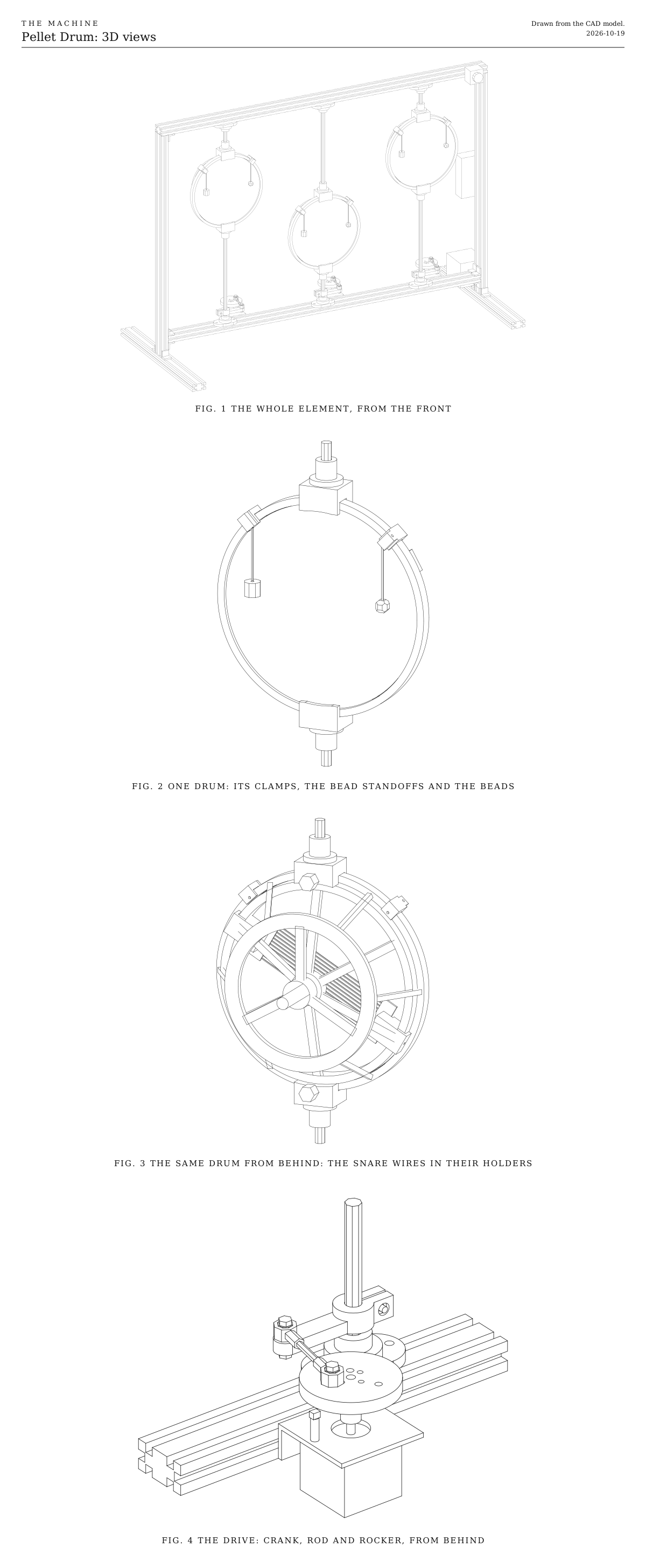
3D views. The whole element from the front, one drum from the front and from behind, and the drive that rocks it. Drawn from the CAD model.
Fig. 13D views. The whole element from the front, one drum from the front and from behind, and the drive that rocks it. Drawn from the CAD model.
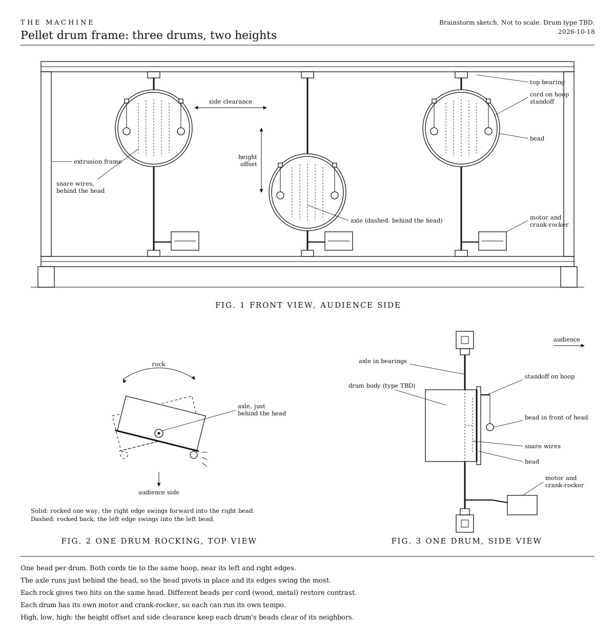
Pellet drum frame, three drums at two heights. The layout the model follows. Front view, one drum rocking from above, one drum from the side.
Fig. 2Pellet drum frame, three drums at two heights. The layout the model follows. Front view, one drum rocking from above, one drum from the side.
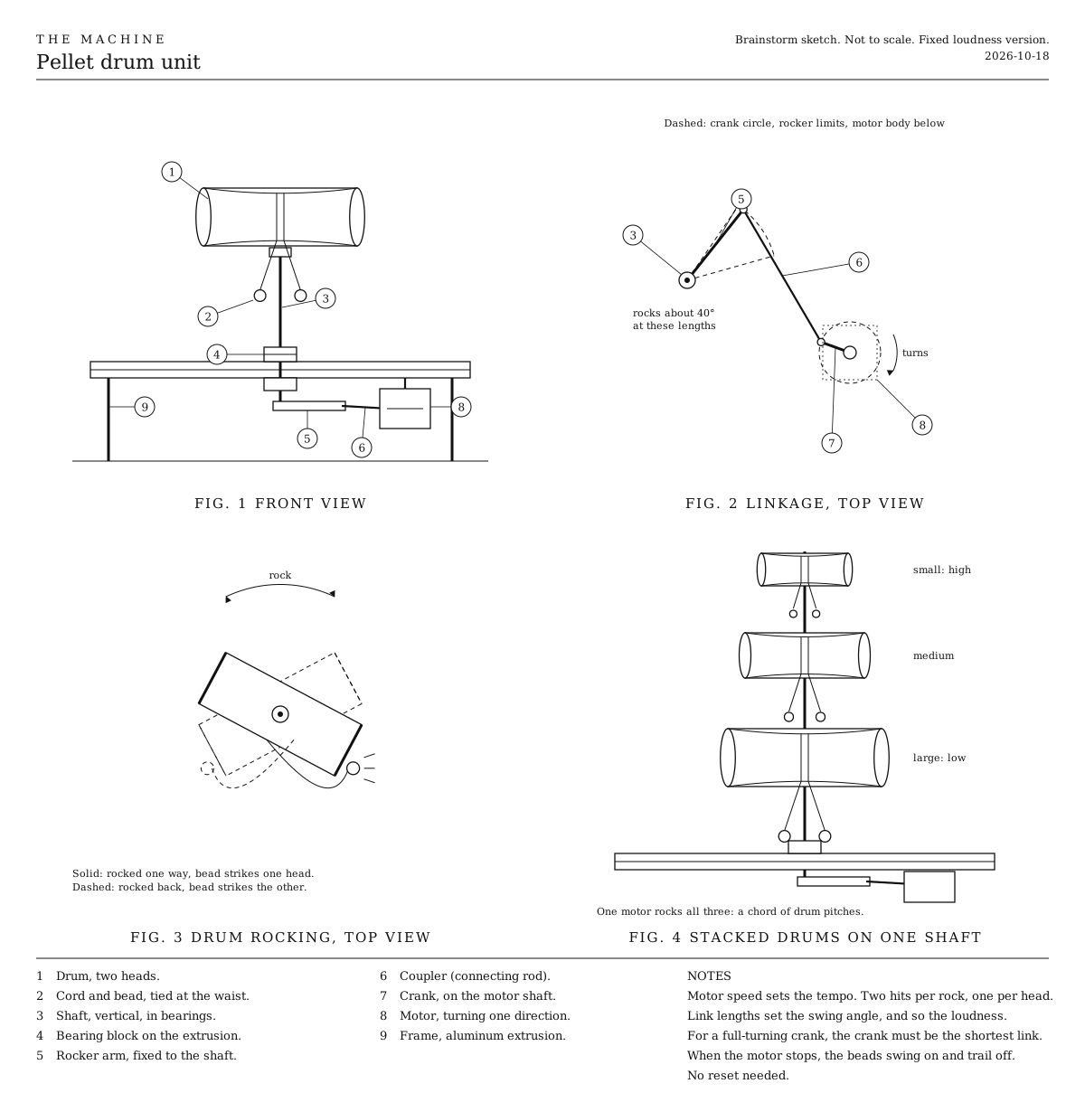
First concept. A small damaru-style drum on a shaft.
Fig. 3First concept. A small damaru-style drum on a shaft.

How it works

  • Three small single-headed drums hang in a V-slot frame, each on its own vertical axle, at high, low and high heights. We started with 8 inch Rototoms; the choices below cover the alternatives.
  • One head per drum faces the audience. The axle runs just behind the head, so the head pivots in place and its left and right edges swing toward and away from the audience.
  • Two beads give two hits a rock. Each bead hangs on a cord from a small standoff clipped on the hoop, just in front of the head near one edge. Rocking one way swings that edge forward into its bead; rocking back swings the other edge into the other bead.
  • The head does the hitting. The bead hangs still, the head swings into it, and the bead bounces off and swings back by itself. It hits cleanly, once a rock, only when the drum rocks faster than the bead would swing on its own, so the cord’s length sets the range of tempos it plays well. Slower than that, each hit becomes a soft double tap.
  • The crank sets the swing. Each drum’s stepper turns a crank, and a short rod with a ball joint at each end rocks an arm clamped to the axle. One turn of the crank is one rock and two hits, so motor speed is tempo. The hole the rod uses on the crank sets how far the drum swings, and so how hard the beads hit.
  • It plays softly. With the middle hole at 150 turns a minute, each drum hits five times a second and the beads strike at about 0.6 m/s, as hard as dropping one from 2 cm. Snare wires and a ringing head carry it.
  • Different beads, different hits. A wood bead on one side and a steel one on the other give each rock a tok and a tick. Sliding the standoffs up the hoop moves the hits toward the middle of the head, for a fuller sound.
  • Snare wires press against the back of the head in two printed holders, so every hit has a sizzle under it.
  • When a motor stops, its beads swing on and trail off, with a few last soft hits. No reset is needed.
  • Each drum keeps its own time. An ESP32-S3 listens for the shared wireless signal and drives the three steppers through quiet drivers. A magnet in each crank passes a hall sensor once a turn, so the code knows where each crank is and can lock each drum’s hits to the beat. It runs from the shared power-tool battery.

Layout

The three drums sit in one rectangle at two heights, high, low and high. The height offset and the side clearance keep each drum’s beads clear of its neighbors. Each drum has its own motor, so each can run its own tempo, drift and lock.

Ways to play

  • Lock them together. All three play one tempo, rocking in step, or with the middle drum half a turn behind the outer two so their hits interleave.
  • Give each its own tempo. Three speeds at once drift against each other and lock back into step.
  • Swell. Speed up through the clean range and the hits come faster and harder, up to about 190 turns a minute with 60 mm cords.
  • Flutter. Below the clean range, the double taps blur into a soft roll.

Notes

  • This is a first design. Expect one round of fitting.
  • The beads’ motion in the 3D model is simulated from the physics, with guesses for how much bounce the head gives back and how much the cord damps the swing. A test build will give the real figures.
  • The Rototom in the model is a generic stand-in. Measure your drum’s hoop before printing the clamps; its size is at the top of the CAD script.
  • Costs in the parts list are rough estimates for budgeting, not checked prices. They add up the version we started with.

References

Parts

Ingredients

KindPartQtySourceEachFile
PrintedDrum clamp, grips the hoop and carries the axle's flange coupling6··STL
PrintedBead standoff, clips on the hoop and holds a cord in front of the head6··STL
PrintedSnare holder, presses one end of the snare wires against the headYour choice: see The snares6··STL
PrintedRocker arm, clamps on the axle above the bottom bearing3··STL
PrintedCrank, with three holes for the three swings3··STL
BoughtRemo Rototom, 8 inch, usedYour choice: see The drum3·$40.00
BoughtSnare wires, 8 inchYour choice: see The snares3·$15.00
BoughtWood bead, about 16 mm, with a hole throughYour choice: see The beads3·$1.00
BoughtStainless steel bead, about 12 mm, with a 2 to 3 mm holeYour choice: see The beads3·$1.00
BoughtBraided nylon cord, about 1.5 mmYour choice: see How long the cords areAbout 15 cm a bead, with room for the knots.1·$3.00
BoughtSteel rod, 10 mm, 600 mm longChrome-plated linear rod is straight and hard. Cut into six lengths: for each high drum about 275 mm below and 75 mm above; for the low drum about 95 mm below and 255 mm above. Some sellers cut to length.2·$8.00
BoughtFlange bearing, KFL000 (two-bolt, 10 mm bore)6·$3.00
BoughtRigid flange coupling, 10 mm boreJoins each length of rod to a drum clamp.6·$4.00
BoughtSelf-adhesive rubber strip, about 2 mm thickLines the clamps' grips, so the hoop doesn't buzz against them.1·$3.00
BoughtM5 thumb screws, about 25 mmOne in each clamp's back jaw, to pinch the hoop.6·$0.50
BoughtNEMA 17 stepper motor, 40 mm bodyYour choice: see The motor3·$12.00
BoughtNEMA 17 L-bracket3·$3.00
BoughtRigid flange coupling, 5 mm boreJoins each crank to its motor's shaft.3·$3.00
BoughtM4 rod ends (ball joints), with a short M4 threaded rodTwo to each rod, about 60 mm between the balls. One is threaded the other way on some sets, which makes the length easy to adjust.6·$2.00
BoughtHall effect switch, A3144 or similar, the bare three-leg part, with a 6 x 3 mm neodymium magnetOne under each crank, on a 15 mm M3 nylon standoff.3·$1.00
BoughtTMC2209 stepper driverQuiet enough that the motors don't whine over the drums.3·$6.00
BoughtElectrolytic capacitor, 100 µF, 35 VOne across each driver's motor supply, to soak up the spikes the motor sends back.3·$1.00
BoughtESP32-S3 development boardThe S3, not the classic ESP32, because three motors and three sensors need more pins than a classic board has free.1·$8.00
BoughtBattery adapter for the shared power-tool platform, and a 5 V buck converterThe stepper drivers run from the battery, through the fuse, the stop button and the relay. The ESP32 and the hall sensors take 5 V.1·$15.00
BoughtThe listener parts every element carries, as on the Control pageA blade fuse holder and 3 A fuse, a latching stop button with a spare contact, the status light, the number switches and their resistors. The stop switch under Choices has a plain two-pole switch in place of the stop button.1Link$12.00
BoughtMomentary push button, normally open, for the test buttonA short press plays each note once, and a long press relearns what the element can by itself. Any small panel button that closes while it's pressed will do.1·$1.00
BoughtRelay module, 5 V, high-level trigger, contacts rated 10 AThe switch all three motors' power goes through. It stands in for the MOSFET the Control page also allows, because a MOSFET module switches the ground side, which would leave the stepper drivers grounded only through the ESP32.1·$2.00
BoughtSmall project box, for the electronicsYour choice: see The electronics1·$5.00
BoughtAluminum extrusion, 20 x 40 mm V-slot, 1000 mm, for the top bar1·$18.00
BoughtAluminum extrusion, 20 x 40 mm V-slot, 960 mm, for the bottom bar1·$17.00
BoughtAluminum extrusion, 20 x 40 mm V-slot, 660 mm, for the uprights2·$12.00
BoughtAluminum extrusion, 20 x 40 mm V-slot, 440 mm, for the feet2·$8.00
BoughtCorner brackets for 20 mm V-slot, with screws and T-nutsTwo join each upright to its foot, four hold each end of the bottom bar, and two hold each end of the top bar.16·$1.00
BoughtM5 screws, T-nuts and washers, assortedThe bearings, the motor brackets, the electronics box, the stop button and the battery adapter.1·$6.00
BoughtM3 and M4 screws and nuts, M3 grub screws, and heat-set insertsTwenty-four M4 and six M5 inserts for the clamps. M4 screws for the flange couplings, the rocker clamps and the rod ends; M3 screws for the crank couplings; M3 grub screws for the standoffs and snare holders.1·$8.00
Total$476.00

Tools

  • 3D printer, PETG
  • Hex keys, 2, 2.5, 3 and 4 mm
  • Soldering iron, for the heat-set inserts and the wiring
  • A hacksaw and a file, for the rod, unless it comes cut
  • A drum key, to even the heads
  • A multimeter, to set the 5 V converter
  • A phone, for a tuner app and a slow-motion video of the beads

Choices

Decisions that are yours to make. Where we started is the version in the 3D model and the ingredients: a starting point, not the right answer.

The drum

What do the beads strike?

Rototom, 8 inch, usedWhere we started

SoundA bright, short tom note that you tune by spinning the drum

Cheap used, single-headed and open at the back, so the snare wires can reach the head. Held by its hoop, so nothing gets drilled.

Rototoms in three sizes, 6, 8 and 10 inch

SoundThree distinct pitches at once, like a chord

Put the 10 inch in the low middle place, where there's the most room. A bigger drum is heavier to rock, and each size needs its clamps resized.

Frame drum, 8 to 10 inch

SoundA deep, soft boom with a long ring

The lightest, so the motor barely works. Its pitch is fixed, and with nothing behind the head, the snare holders need another way to fix on.

Micro snare, 8 inch

SoundA tight crack, with the snare buzz built in

$100 or more each, and heavier to rock. Its own snares replace the holders, and its shell is deeper, so the clamps need resizing.

The clamps grip the hoop at the top and bottom, so the axle sits just behind the head whatever the drum. A different hoop needs the clamps resized, which is one number at the top of the CAD script.

The snares

What buzzes behind the head?

8 inch snare wires, in printed holdersWhere we started

SoundA dry sizzle under every hit

The holders clip on the ring under the head and press the wires against it. How hard they press sets how much the wires buzz.

Remo Rhythm Lid snare clip

SoundMuch the same buzz

A bought clip, made for buckets. Its fit on a small Rototom is untested.

None

SoundA clean tom note, where the beads' click stands out

Cheapest. Easy to try, since the holders come off with one screw each. One drum without snares gives the frame a contrast.

The beads

What strikes the head? Each drum has two, and they needn't match.

Wood, about 16 mmWhere we started

SoundA warm tok

Cheap craft beads, and kind to the head.

Stainless steel, about 12 mmWhere we started

SoundA bright crack

Jewelry spacer beads, with a hole through. Over time they can dent a coated head.

Hard plastic or resin

SoundA light, dry tick

Light, so it hits softly. A bigger bead hits harder.

Knotted leather or cord

SoundA soft thump, the voice of a real damaru

A big knot, or a bead wrapped in leather. The quietest of these.

Different beads on the two cords make the two hits in each rock sound different. Matching beads make an even pair.

How long the cords are

How far below its standoff does each bead hang?

Short, about 45 mm

SoundClean single hits from about 150 to 210 turns a minute, 5 to 7 hits a second

Suits fast tempos only. Slower, each hit becomes a soft double tap.

Medium, about 60 mmWhere we started

SoundClean single hits from about 120 to 210 turns a minute, 4 to 7 hits a second

The widest range of tempos.

Long, about 90 mm

SoundClean single hits from about 110 to 180 turns a minute, with a lazier swing between them

Slide the standoffs up the hoop so the longer cord still lands the bead on the head.

A bead strikes cleanly only when the drum rocks faster than the bead would swing on its own. Slower than that, it chatters against the head in soft double taps, which can be a sound of its own. The length sets the range of tempos, not the loudness.

How far it rocks

Which hole on the crank does the rod use?

Inner hole, about 9 degrees either way

SoundSoft hits, about as hard as dropping the bead from a few millimeters to 2 cm

The easiest on the motor. Clean hits from about 105 turns a minute up past 210.

Middle hole, about 15 degreesWhere we started

SoundMedium hits, as if dropped from 1 to 6 cm, growing with tempo

Clean hits from about 120 to 210 turns a minute.

Outer hole, about 21 degrees

SoundThe loudest, as if dropped from 2 to 7 cm

Clean hits only from about 120 to 180 turns a minute, and the motor works hardest.

The ranges are for 60 mm cords. Each hole sits at a different angle on the crank, so changing holes moves when the hits land against the hall sensor's pulse, and the code needs to know which hole is used. After changing holes, adjust the rod's length so the drum rocks evenly either side of facing the audience.

The motor

What turns the crank?

NEMA 17 stepperWhere we started

SoundA faint hum on a TMC2209 driver

Holds the tempo and the timing exactly, straight from the shared clock. A magnet in the crank passes a hall sensor once a turn, so the code knows where the crank is. Fits the shared wiring as it is.

Geared DC motor, with an encoder

SoundA gear whine that rises with the tempo

Cheaper and stronger. The code has to hold the tempo by feedback, so it drifts and catches up instead of locking.

A stepper on the axle, with no crank

SoundEvery hit can be louder or softer

The motor swings the drum itself, so accents, single hits and rests become possible. It reverses the drum's weight on every hit and works much harder; a belt with a 3 to 1 reduction helps.

The stop switch

What cuts the motors' power at the element?

Latching emergency-stop button, with a spare contactWhere we started

The red mushroom head anyone nearby knows to hit. It stays down until it's twisted to release, so the element can't start again by accident. Its main contact cuts the power and its spare contact tells the ESP32. About $8.

Two-pole power switch, a rocker or a toggle

Smaller, plainer and cheaper, about $2. One pole cuts the power and the other tells the ESP32, so it does the same job. It doesn't read as a stop to someone who doesn't know the Machine, and it switches back on as easily as off. Rate its contacts above what the element draws, as the button's are.

Keep the second pole either way. The ESP32 knows where each crank is only by counting the steps it sends, so the second pole is how it learns the power was cut, and finds each crank's magnet again before it moves. Without it, a drum turned by hand while it was off would hit off its beat. Either way the relay stays, since it's how a stop from the Bridge reaches the element when no one is at it. A two-pole switch wires as the button does: one pole in place of the main contact, from 11 to 12, and the other in place of the spare contact, from 13 to 14.

Print

Material
PETG
Layers
0.2 mm
Walls
4
Infill
40%

Every part fits a 150 mm bed and prints without supports. PETG shrugs off a warm motor and the constant reversing; PLA is fine for a first try. Print the clamps in a test pair first and check their grip on your hoop.

The printed parts

  • Drum clamp, grips the hoop and carries the axle's flange coupling× 6

    Which way up
    Flat top down, with the curved grip facing up
    Supports
    None
    Time
    About 45 minutes

    Four M4 heat-set inserts go into its flat top for the flange coupling, and an M5 insert into its back jaw for the thumb screw.

    STL ↓
  • Bead standoff, clips on the hoop and holds a cord in front of the head× 6

    Which way up
    Bridge down, with the jaws and the arm standing up
    Supports
    None
    Time
    About 10 minutes

    The same part serves both sides of the drum.

    STL ↓
  • Snare holder, presses one end of the snare wires against the head× 6

    Which way up
    Back face down
    Supports
    None
    Time
    About 30 minutes
    STL ↓
  • Rocker arm, clamps on the axle above the bottom bearing× 3

    Which way up
    Flat, as it sits on the axle
    Supports
    None
    Time
    About 30 minutes

    An M4 nut sinks into the side of its clamp ear.

    STL ↓
  • Crank, with three holes for the three swings× 3

    Which way up
    Flat, the magnet's pocket down
    Supports
    None
    Time
    About 45 minutes

    The magnet's pocket on the underside sits under the middle hole. Press the magnet in with a dab of glue.

    STL ↓

Assembly

  1. 1

    Join each upright to its foot with two corner brackets, one in front and one behind.

  2. 2

    Fit the bottom bar between the uprights, its underside 40 mm above the feet, with two brackets above and two below at each end.

  3. 3

    Sit the top bar across the tops of the uprights and fix it with two brackets at each end.

    CheckThe frame stands square and doesn't rock on a flat floor, and both bars are level.

  4. 4

    Tune each drum before it goes in the frame. Hold its center bolt and spin the drum to the pitch you want, then tap around the edge and even the head with the drum key.

    CheckTapped near each tension rod, the head sounds the same pitch.

  5. 5

    Clip the two snare holders on the ring under the head, opposite each other, between tension rods. Set the snare wires' end plates in their pockets and tighten the holders' screws.

    TrickyPressed too hard, the wires choke the head; too lightly, they rattle on their own. Ease the screws until the buzz just follows the hit.

    CheckThe wires lie flat against the back of the head, and a tap on the head buzzes them evenly.

  6. 6

    Line the grip of each drum clamp with rubber strip and melt in its heat-set inserts. Turn the drum until a gap between tension rods is at the top, then fit one clamp on the hoop there and one at the bottom, and tighten their thumb screws.

    TrickyThe clamps must sit exactly opposite each other, or the drum hangs crooked on its axle. A drum with six tension rods has a gap opposite every gap. With five, one clamp has to straddle a rod; cut a notch in it.

    CheckThe two clamps' flat faces are level and exactly above one another.

  7. 7

    Screw a flange coupling onto each clamp. Slide a rocker arm onto each drum's lower length of rod, then push the rod into the lower coupling and the upper length into the upper one, and tighten the couplings' set screws.

  8. 8

    Slide a flange bearing onto the free end of each rod, then lift each drum into the frame and bolt its bearings into the front slots, the lower one on top of the bottom bar and the upper one under the top bar. We started with the axles 200, 500 and 800 mm from the left end, the outer drums high and the middle one low.

    TrickyLine each pair of bearings up one exactly above the other before tightening them. Off by a few millimeters, the axle binds and the drum sticks at one end of its swing.

    CheckPushed by hand, the drum turns freely on its axle and stays wherever you leave it.

  9. 9

    Hang the beads. Clip a bead standoff on the hoop near the top left and another near the top right, tie a bead onto each cord, and thread the cord through the standoff's hole so the middle of the bead hangs your chosen length below it.

    TrickyHow big the gap is hardly matters, but a bead resting on the head buzzes instead of striking. If one touches, shorten its cord or move its standoff.

    CheckEach bead hangs just clear of the head, near its edge, and doesn't touch it.

  10. 10

    Bolt each motor to an L-bracket, shaft up, and the bracket to the back of the bottom bar, with the motor's shaft about 48 mm to the right of the axle and 60 mm behind it.

  11. 11

    Press a magnet into each crank's pocket, fix a 5 mm flange coupling on each motor shaft, and screw the crank to it.

  12. 12

    Clamp each rocker arm on its axle just above the bottom bearing, pointing right, toward the motor, with the drum facing the audience.

  13. 13

    Build each rod from two rod ends on a short threaded rod, about 60 mm between the balls. Bolt one end to the rocker's tip and the other to the crank's middle hole.

    TrickyIf it rocks farther one way than the other, the rod is the wrong length. Turn one rod end half a turn at a time until the two sides match, then lock its nut.

    CheckTurn the crank by hand. The drum rocks evenly either side of facing the audience, about 15 degrees each way.

  14. 14

    Fit each hall sensor on a nylon standoff on the motor bracket, under the crank, where the magnet passes over it when the drum faces the audience.

    TrickyThe A3144 answers to one pole of the magnet only. Test the magnet against the sensor before gluing it in, and flip it if the sensor doesn't switch.

    CheckWith the sensor wired, its output drops low as the magnet passes, and nowhere else in the turn.

  15. 15

    Wire it in the box on the right upright, following the wire list under Wiring. The fuse comes first, then the 5 V converter for the ESP32 and the sensors, and the stop button and the relay for the motors' power. Each motor goes to its own driver and each sensor to its own ESP32 input. Join all the grounds.

    TrickySet the 5 V converter with a multimeter before the ESP32 or the sensors are connected. Most come set higher, and more than about 6 V destroys the board.

    CheckWith the battery in and no code running, each crank turns by hand and the ESP32's light is on. Press the stop button, release it, and nothing moves.

  16. 16

    Run each motor with a simple step test on the ESP32, slowly at first, then up to 150 turns a minute, and watch the beads.

    TrickyBelow the cords' range the hits turn into soft double taps, which is the physics, not a fault. Find where the clean hits begin on each drum before deciding anything's wrong.

    CheckAt speed, each bead strikes once a turn with a clean tap, and the drum doesn't knock at the ends of its swing. A slow-motion phone video shows it best.

Wiring

The fuse comes first, right after the battery. The ESP32-S3 and the three hall sensors run from the 5 V converter. All three motors' power goes through the stop button and then one relay, so either one cuts it. The status light, the number switches and the battery reading are wired the same way on every element, so they're on the Control page, not here.

Wiring · Pellet Drum
PowerSignalMotorGround, all joinedPins drawn faint are left empty.

Wire list

  1. Battery adapter, +

    Fuse, 3 A, in

    PowerRed, 16 AWG

    As short as the adapter allows. Nothing connects ahead of the fuse.

  2. Fuse, 3 A, out

    5 V converter, IN+

    PowerRed, 22 AWG

  3. Fuse, 3 A, out

    Stop button, 11

    PowerRed, 18 AWG

  4. Stop button, 12

    Relay module, COM

    PowerRed, 18 AWG

    The stop button's main contact opens when pressed, cutting the motors' power itself, so a program that hangs can't ignore it.

  5. Relay module, NO

    TMC2209 driver, left drum, VM

    PowerRed, 18 AWG

    One wire from the relay to each driver, or a short bus bar in the box.

  6. Relay module, NO

    TMC2209 driver, middle drum, VM

    PowerRed, 18 AWG

  7. Relay module, NO

    TMC2209 driver, right drum, VM

    PowerRed, 18 AWG

  8. Capacitor, 100 µF, left drum, +

    TMC2209 driver, left drum, VM

    PowerThe capacitor's own leg

    Solder each capacitor's legs straight onto its driver's VM and GND pins. The stripe on its side marks the − leg.

  9. Capacitor, 100 µF, middle drum, +

    TMC2209 driver, middle drum, VM

    PowerThe capacitor's own leg

  10. Capacitor, 100 µF, right drum, +

    TMC2209 driver, right drum, VM

    PowerThe capacitor's own leg

  11. 5 V converter, OUT+

    ESP32-S3 board, 5V

    PowerRed, 22 AWG

    Only once the converter is set to 5 V.

  12. 5 V converter, OUT+

    Relay module, VCC

    PowerRed, 22 AWG

  13. 5 V converter, OUT+

    Hall sensor, left drum, VCC

    PowerRed, in a three-core cable to each sensor

    The A3144 needs at least 4.5 V, so the sensors take 5 V, not 3.3 V.

  14. 5 V converter, OUT+

    Hall sensor, middle drum, VCC

    PowerRed, in the sensor's cable

  15. 5 V converter, OUT+

    Hall sensor, right drum, VCC

    PowerRed, in the sensor's cable

  16. ESP32-S3 board, 3V3

    TMC2209 driver, left drum, VDD

    PowerRed, 22 AWG

    The drivers' logic runs at the ESP32's 3.3 V, so their signals match.

  17. ESP32-S3 board, 3V3

    TMC2209 driver, middle drum, VDD

    PowerRed, 22 AWG

  18. ESP32-S3 board, 3V3

    TMC2209 driver, right drum, VDD

    PowerRed, 22 AWG

  19. Battery adapter, −

    5 V converter, IN−

    GroundBlack, 22 AWG

  20. Battery adapter, −

    TMC2209 driver, left drum, GND

    GroundBlack, 18 AWG

    Each motor's return. Use each driver's GND pin next to VM.

  21. Battery adapter, −

    TMC2209 driver, middle drum, GND

    GroundBlack, 18 AWG

  22. Battery adapter, −

    TMC2209 driver, right drum, GND

    GroundBlack, 18 AWG

  23. Capacitor, 100 µF, left drum, −

    TMC2209 driver, left drum, GND

    GroundThe capacitor's own leg

  24. Capacitor, 100 µF, middle drum, −

    TMC2209 driver, middle drum, GND

    GroundThe capacitor's own leg

  25. Capacitor, 100 µF, right drum, −

    TMC2209 driver, right drum, GND

    GroundThe capacitor's own leg

  26. 5 V converter, OUT−

    ESP32-S3 board, GND

    GroundBlack, 22 AWG

  27. ESP32-S3 board, GND

    TMC2209 driver, left drum, GND

    GroundBlack, 22 AWG

    Each driver's other GND pin, next to VDD.

  28. ESP32-S3 board, GND

    TMC2209 driver, middle drum, GND

    GroundBlack, 22 AWG

  29. ESP32-S3 board, GND

    TMC2209 driver, right drum, GND

    GroundBlack, 22 AWG

  30. Relay module, GND

    ESP32-S3 board, GND

    GroundBlack, 22 AWG

  31. Resistor, 10 kΩ, 2

    ESP32-S3 board, GND

    GroundThe resistor's own leg

  32. Stop button, 14

    ESP32-S3 board, GND

    GroundBlack, 22 AWG

  33. Test button, 2

    ESP32-S3 board, GND

    GroundBlack, 22 AWG

  34. Hall sensor, left drum, GND

    ESP32-S3 board, GND

    GroundBlack, in the sensor's cable

  35. Hall sensor, middle drum, GND

    ESP32-S3 board, GND

    GroundBlack, in the sensor's cable

  36. Hall sensor, right drum, GND

    ESP32-S3 board, GND

    GroundBlack, in the sensor's cable

  37. Hall sensor, left drum, OUT

    ESP32-S3 board, GPIO 21

    SignalAny color, in the sensor's cable

    The sensor pulls the pin low as the magnet passes. Turn on the ESP32's own pull-up for these three pins.

  38. Hall sensor, middle drum, OUT

    ESP32-S3 board, GPIO 41

    SignalAny color, in the sensor's cable

  39. Hall sensor, right drum, OUT

    ESP32-S3 board, GPIO 47

    SignalAny color, in the sensor's cable

  40. Stop button, 13

    ESP32-S3 board, GPIO 4

    SignalAny color, 22 AWG

    The stop button's spare contact, so the ESP32 knows it's been pressed.

  41. Test button, 1

    ESP32-S3 board, GPIO 14

    SignalAny color, 22 AWG

    The test button. The ESP32's own pull-up holds the pin high until it's pressed, so nothing else goes on this pin.

  42. ESP32-S3 board, GPIO 16

    TMC2209 driver, left drum, STEP

    SignalAny color, 22 AWG

  43. ESP32-S3 board, GPIO 17

    TMC2209 driver, left drum, DIR

    SignalAny color, 22 AWG

  44. ESP32-S3 board, GPIO 38

    TMC2209 driver, middle drum, STEP

    SignalAny color, 22 AWG

  45. ESP32-S3 board, GPIO 39

    TMC2209 driver, middle drum, DIR

    SignalAny color, 22 AWG

  46. ESP32-S3 board, GPIO 40

    TMC2209 driver, right drum, STEP

    SignalAny color, 22 AWG

  47. ESP32-S3 board, GPIO 42

    TMC2209 driver, right drum, DIR

    SignalAny color, 22 AWG

  48. ESP32-S3 board, GPIO 18

    TMC2209 driver, left drum, EN

    SignalAny color, 22 AWG

    One pin turns all three motors on and off. Low turns them on. The ESP32 holds it high while the element waits, so the motors don't hum.

  49. ESP32-S3 board, GPIO 18

    TMC2209 driver, middle drum, EN

    SignalAny color, 22 AWG

  50. ESP32-S3 board, GPIO 18

    TMC2209 driver, right drum, EN

    SignalAny color, 22 AWG

  51. ESP32-S3 board, GPIO 5

    Relay module, IN

    SignalAny color, 22 AWG

  52. Resistor, 10 kΩ, 1

    Relay module, IN

    SignalThe resistor's own leg

    Holds the relay off while the ESP32 starts, when its pins float.

  53. TMC2209 driver, left drum, 1A

    Stepper motor, left drum, A1

    MotorThe motor's own cable

    On each driver, 1A and 1B go to one coil, 2A and 2B to the other.

  54. TMC2209 driver, left drum, 1B

    Stepper motor, left drum, A2

    MotorThe motor's own cable

  55. TMC2209 driver, left drum, 2A

    Stepper motor, left drum, B1

    MotorThe motor's own cable

  56. TMC2209 driver, left drum, 2B

    Stepper motor, left drum, B2

    MotorThe motor's own cable

  57. TMC2209 driver, middle drum, 1A

    Stepper motor, middle drum, A1

    MotorThe motor's own cable

  58. TMC2209 driver, middle drum, 1B

    Stepper motor, middle drum, A2

    MotorThe motor's own cable

  59. TMC2209 driver, middle drum, 2A

    Stepper motor, middle drum, B1

    MotorThe motor's own cable

  60. TMC2209 driver, middle drum, 2B

    Stepper motor, middle drum, B2

    MotorThe motor's own cable

  61. TMC2209 driver, right drum, 1A

    Stepper motor, right drum, A1

    MotorThe motor's own cable

  62. TMC2209 driver, right drum, 1B

    Stepper motor, right drum, A2

    MotorThe motor's own cable

  63. TMC2209 driver, right drum, 2A

    Stepper motor, right drum, B1

    MotorThe motor's own cable

  64. TMC2209 driver, right drum, 2B

    Stepper motor, right drum, B2

    MotorThe motor's own cable

Get these right

Set the converter first
Most 5 V converters come set higher. Turn its screw with the battery in and a multimeter on its output until it reads 5.0 V, and only then connect the ESP32 and the sensors. More than about 6 V destroys the board.
Use the bare sensor, not a module
Hall sensor modules usually add their own pull-up resistor to their supply, which would put 5 V on the ESP32's pin and can destroy it. The bare three-leg A3144 only ever pulls the pin down, so it's safe on 5 V.
Finding the motor's coils
Motor wire colors vary by maker. Touch two wires together and turn the shaft by hand; if it suddenly turns stiffly, those two are one coil. If a motor runs backwards, swap the two wires of one coil.
Never unplug a motor with power on
Disconnecting a running stepper can destroy its driver. Press the stop button first.
The pins
Any free ESP32-S3 pins will do, except 0, 3, 45 and 46, which the board reads as it starts, 19 and 20, which are its USB port, and 35 to 37 on boards with eight megabytes of extra memory (marked R8). The pins here leave 1 and 6 to 15 free for the status light, the number switches, the test button and the battery reading. If you use others, the code needs to know.

Mounting

Everything fixes to the V-slot frame with T-nuts and screws, so any part can slide to a new place or come off with a hex key. Each drum is a module, two bearings, an axle and a motor, that slides along the bars to change the spacing.

The frame
Two uprights stand on two feet, with a bottom bar between them 40 mm above the feet and a top bar across their tops. All are 20 x 40 mm V-slot, joined by corner brackets.
The axles
Each turns in two flange bearings, one on top of the bottom bar and one under the top bar, both bolted into the front slot with two T-nuts. They slide along the slot to set the spacing.
The drums
Each hangs on its axle by the two clamps on its hoop. Its height is wherever the couplings sit on the rod, so high and low are set by where you cut the rod.
The motors
Each motor hangs from an L-bracket on the back of the bottom bar, shaft up, just to the right of its axle. Two M5 screws go into T-nuts in the bar's back slot.
The hall sensors
Each sits on a nylon standoff on its motor bracket, under the crank.
The electronics
The box sits on the back of the right upright, about 30 cm up, on two T-nuts. The motor and sensor cables run to it along the bottom bar's back slot.
The stop button
It sits in its own housing on the front of the top bar near the right end, where a hand finds it without reaching past a drum.
The battery
The adapter sits on the right foot, behind the upright, on two T-nuts, so the pack slides on and off without moving anything else.
The wires
Clip-in slot covers hold the cables inside the extrusion's slots, out of sight and clear of the rocking drums.

The electronics

Hidden in a box, or on show?

Closed boxWhere we started

A small project box, bought or printed, bolted to the upright. Tidy and protected, but it hides the electronics.

Open plate

The boards on standoffs on a flat plate on the upright, with the wires dressed along the slot. The electronics become part of the look. It wants neat wiring, and nothing guards it from knocks.

DIN rail

A short length of 35 mm DIN rail on T-nuts, with each board in a snap-on holder. It looks like a control panel, and any board comes off with a flick. The holders add a few dollars.

Whichever you pick, keep the stop button on the outside, where anyone can reach it.

Tuning

Tuning

The test button
A short press turns each drum once, left, middle, then right. Hold it for two seconds and it turns each crank to its magnet, so it knows where each drum faces again. It works only while the element is resting, with no Bridge in range or with the Bridge holding it silent. While it plays or is stopped, the button does nothing. A stop ends a test at once, and pressing again ends one early. Which crank hole is used is still told to the firmware by hand.
Soft double taps instead of clean hits
The drum is rocking slower than the bead wants to swing. Speed up, or use shorter cords; the clean range for 60 mm cords starts about 120 turns a minute. Or keep it, since a slow rock gives a soft, rolling flutter of its own.
Hits turning ragged at the top of the range
The bead can't get back to the head in time. Slow down, use a smaller hole on the crank, or use longer cords. With 60 mm cords the hits are loudest around 190 turns a minute and soften after that.
A buzz between hits
A bead is resting on the head, or the snare wires are loose. Shorten the cord a little, or tighten the snare holders.
A fuller, deeper hit
Slide the standoffs up the hoop, toward the top, so the beads land nearer the middle of the head. The edge moves less there, so the hits come a touch softer.
Tok and tick at different loudness
The two beads differ, which is the point. If they're the same and still uneven, the drum isn't rocking evenly. Adjust the rod's length until it is.
The snares choke the note
The holders press too hard. Ease their screws, or leave the snares off one drum for contrast.
A knock at the ends of each rock
Something has play in it. Tighten the clamps' thumb screws and the couplings' set screws, check the rubber strip is in the clamps, and look for slack in the rod ends.
The drum lurches at each reversal
Something heavy is off the axle's line. Counterweight it on the other side of the axle so the drum turns smoothly.
The frame shakes or walks
Three drums rocking in step push the frame back and forth together. Run the middle drum half a turn out of step with the outer two, so their pushes partly cancel, or bolt the feet down.
The hits drift off the beat
A motor is skipping steps. Raise its driver's current a little, use a smaller hole, or bolt a few steel washers under the crank as a small flywheel. The hall sensor's pulse also lets the code notice and catch up.
A whine under the drums
A stepper driver isn't in its quiet mode. The TMC2209 has a near-silent mode for slow, steady turning.

Variations

A chord of three sizes
Rototoms of 6, 8 and 10 inches give three pitches at once. The 10 inch goes in the low middle place, where there's room; the clamps are resized for each hoop.
Three drums on one shaft
The first concept stacks the drums on one axle, so one motor rocks all three. It's cheaper and simpler, but the three play only together.
A real damaru
The original pellet drum is a small two-headed drum on a vertical shaft, with beads on cords tied at its waist. One motor twists it back and forth, and the beads strike both heads, one on each twist. It's smaller and gives the traditional sound.
A slotted crank
A slot from 8 to 18 mm in place of the three holes lets the swing be set anywhere. It needs a firm clamp on the crank pin, or the pin creeps along the slot under the reversing pull.
More drums, or wider spacing
Each drum is a module of two bearings, an axle and a motor. A longer pair of bars takes a fourth or fifth, and the bearings slide along the slots to any spacing.