Skip to content

The Machine · Recipes

Motor Pick

Design stage

Updated 2026-10-20

A stepper turns a small wheel of guitar picks beside a string. A quarter turn is one pluck, a spin is tremolo, and parked, the string rings untouched. It bolts to any string build and listens to Control on its own number.

Loading the model

Drag to turn · scroll to zoom

Printed

3DThe unit, on a length of string build. This is the version we started with, shown on a short length of Lapless Steel's extrusion and string for scale. Only the hub is printed, and it's drawn in orange. The string is drawn thicker than life so it shows. Press Play to watch it pluck, pluck back and play tremolo, slowed down so you can see it.

Overview

Cost, roughly
About $80
Printing
About 1.5 hours
Building
An afternoon
Difficulty
Moderate

Anatomy

1
Energy source
A stepper motor turns a wheel of picks
2
Control
Each quarter turn is one pluck, started early so the string lets go on the beat; spinning plays tremolo
3
Sounding body
The string of whichever element it's mounted on
4
Reset
None needed; it parks with the string between two picks
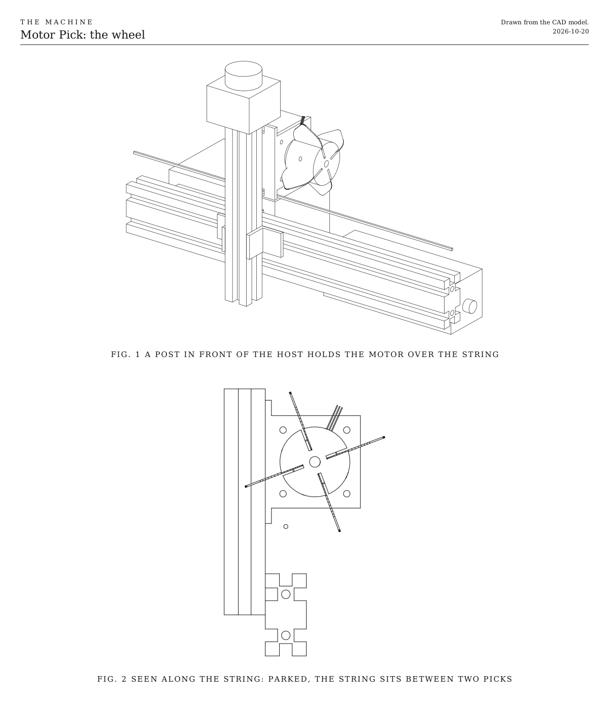
The wheel. A post stands in front of the string build and holds the motor over the string. Seen along the string, the wheel parks with the string halfway between two picks. Drawn from the CAD model.
Fig. 1The wheel. A post stands in front of the string build and holds the motor over the string. Seen along the string, the wheel parks with the string halfway between two picks. Drawn from the CAD model.

How it works

  • A stepper turns a small wheel of guitar picks. Four picks stand out of a printed hub on the motor’s shaft. The shaft runs along the string, above it and a little behind, so each pick sweeps down through the string, mostly sideways, the way a hand plucks.
  • A quarter turn is one pluck. The pick catches the string 1.5 mm deep, bends, and lets it go. Turning back plucks the other way.
  • Parked, the string sits halfway between two picks, so it rings with nothing touching it.
  • Spinning plays tremolo. At four turns a second, that’s 16 plucks a second.
  • It knows where its picks are. The ESP32 counts every step it sends the motor, and a magnet in the hub passes a Hall sensor once a turn to keep the count true. The string lets go a moment after a turn starts, so the ESP32 starts each one that much early, and the pluck lands on the beat.
  • It has its own control. It carries its own ESP32, stepper driver, battery and stop button, and listens to Control on its own number. It can play an open string in rhythm by itself, or pluck alongside the element it’s mounted on while that element changes the note.
  • It makes no sound on a wire of its own. The string belongs to the host, and the host’s pickup hears it.

What the notes mean

The bridge sends notes numbered from 0, and each element decides what its numbers mean. These are the Motor Pick’s.

Note What it does
0 One pluck on the note, turning forward
1 One pluck on the note, turning back
2 Tremolo from this note until the next, faster the louder it’s sent
3 Hold a pick in the string’s path, for strings that move past it, as on the Windmill Arpeggio Machine
4 Park clear of the string

How hard a single pluck sounds is set by the catch, by hand. Loudness only changes how fast the pick snaps through, which changes the attack a little.

Notes

  • This is a first design, drawn but not yet built. The 3D model and the files show the version we started with. Bought parts vary, so check your motor’s bracket and shaft against the numbers in the CAD script.
  • The picks spin fast during tremolo. Press the stop button before reaching in.
  • Costs in the ingredients are rough estimates for budgeting, not checked prices.
  • Firmware comes later. For a first test, any stepper example sketch that turns 400 steps at a time, a quarter turn at 8 microsteps, will pluck.

References

  • Robot guitars such as LEMUR’s GuitarBot and MechBass pluck with a turning wheel of picks, as this does.

Parts

Ingredients

KindPartQtySourceEachFile
PrintedPick hub, holds four picks on the motor's shaft, and the homing magnet1··STL
BoughtNEMA 17 stepper motor, 40 mm body, 5 mm shaft with a flat1·$12.00
BoughtSteel L-bracket for NEMA 17 motorsThe motor bolts to its face with four M3 screws, and its leg bolts to the post.1·$4.00
BoughtV-slot extrusion, 20 x 20 mm, 150 mm, the postLong enough to stand on the table beside a string 23 mm above a 40 mm extrusion. For a higher string, use a longer post.1·$3.00
BoughtCorner brackets for 20 mm V-slot2·$1.00
BoughtM5 screws and T-nuts for 20 mm V-slot8·$0.30
BoughtM3 x 10 set screwsFour pinch the picks, and one grips the shaft.5·$0.20
BoughtGuitar picks, medium nylon, a packYour choice: see The pick's materialStandard teardrop picks, about 30 x 26 mm. Four ride on the wheel; the rest are spares.1·$5.00
BoughtDisc magnet, 5 x 2 mm, neodymium1·$0.30
BoughtHall sensor, A3144, the bare three-legged partIt sees the magnet once a turn, so the ESP32 can find where the picks are.1·$0.50
BoughtESP32-S3 development board1·$8.00
BoughtTMC2209 stepper driverQuiet, which matters with the host's pickup a few centimeters away.1·$6.00
Bought5 V buck converterFor the ESP32, the relay and the Hall sensor. The motor runs from the battery.1·$3.00
BoughtBattery adapter for the shared power-tool platformYour choice: see Its powerThe stepper driver runs from the battery, through the fuse, the stop button and the relay.1·$15.00
BoughtThe listener parts every element carries, as on the Control pageA blade fuse holder and 2 A fuse, a latching stop button with a spare contact, the status light, the number switches and their resistors. The stop switch under Choices has a plain two-pole switch in place of the stop button.1Link$12.00
BoughtMomentary push button, normally open, for the test buttonA short press plays each note once, and a long press relearns what the element can by itself. Any small panel button that closes while it's pressed will do.1·$1.00
BoughtRelay module, 5 V, high-level trigger, contacts rated 10 AThe switch the motor's power goes through.1·$2.00
BoughtResistor, 10 kΩHolds the relay off while the ESP32 starts.1·$0.10
BoughtElectrolytic capacitor, 100 µF, 35 VAcross the driver's motor supply, to soak up the spikes the motor sends back.1·$1.00
BoughtSmall project box, about 120 x 40 x 40 mm, for the electronicsYour choice: see The electronics1·$6.00
Total$84.30

Tools

  • 3D printer, PETG
  • Hex keys, 1.5, 2.5 and 4 mm
  • Soldering iron, for the Hall sensor's wires
  • Five-minute epoxy, for the Hall sensor and the magnet
  • A ruler
  • A phone that films in slow motion, to check the timing

Choices

Decisions that are yours to make. Where we started is the version in the 3D model and the ingredients: a starting point, not the right answer.

What turns the pick

What moves the pick through the string?

A stepper turning a wheel of picksWhere we started

SoundSingle plucks either way, tremolo and rests, each landing where the firmware expects it

One printed hub and a stepper driver. A stepper beside the string can hum into a magnetic pickup, so the firmware switches it off between notes.

A servo flick

SoundEach swing through the string is a pluck, so the strokes alternate one way and back. Tremolo tops out at around 8 plucks a second.

The cheapest and smallest, with no driver board. An MG90S holds a pick in a mini binder clip on its horn, as Lapless Steel and the Windmill Arpeggio Machine are drawn. Its timing is looser, since a hobby servo's speed varies, and it heats up if it keeps tremolo going.

A DC motor turning the wheel

SoundSmooth, endless tremolo, its speed set by the voltage

Cheap and quiet, but it can't put a single pluck on the beat without an encoder, and it needs a different driver.

A solenoid, like a harpsichord's jack

SoundThe quickest single pluck, always the same strength

The pick sits on a hinged tongue that plucks on the way up and folds past the string on the way down. It clacks, and its magnet can click in a nearby pickup. Nothing here is drawn for it yet.

The pick's material

What is the pick made of?

NylonWhere we started

SoundA bright, clear attack, the guitar sound most people expect

Cheap, sold in every music shop, and slightly grippy

Celluloid

SoundA little warmer than nylon, with a glassy click

The classic tortoiseshell-pattern pick. It wears fastest, and its edge goes rough.

Delrin, sold as Tortex

SoundDrier and warmer, with less click

It barely wears. Modern harpsichords use it in place of quill.

Felt or leather

SoundA soft, round attack like a thumb, much quieter

Ukulele felt picks fit the slots. They need a deeper catch.

Mix two kinds on one wheel for two voices. Whichever pick comes round next sets the voice.

The pick's thickness

How stiff is the pick?

Thin, 0.4 to 0.5 mm

SoundSnappy and light, with a papery click, and quieter

Easiest on the motor, and the best for fast tremolo

Medium, 0.6 to 0.75 mmWhere we started

SoundBalanced, clear and full

The usual pick

Heavy, 1 mm and up

SoundLouder, rounder and darker

It pushes harder on the string, so the motor needs more current, and it can snag if it catches deep. The slots take picks up to about 1.2 mm.

How many picks

How many picks ride on the wheel?

Two

SoundHalf the tremolo for the same speed of turning

The widest gap to park in, so it's the most forgiving to set up

FourWhere we started

SoundSingle plucks a quarter turn apart, and tremolo up to 20 or more plucks a second

Room to park the string well clear of both neighbors

Six

SoundThe fastest tremolo, a shimmer

The gaps are narrower, so a parked string sits closer to a pick. Change PICKS in the CAD script and print the hub again.

Where it plucks

Where along the string does it sit?

Close to the bridge

SoundBright, thin and twangy, like playing right by a guitar's bridge

The string moves least there, so set the catch closely

About a fifth of the way from the bridgeWhere we started

SoundThe usual guitar tone, full and clear

Roughly where a guitarist's hand rests

Near the middle

SoundRound and hollow, almost like a flute

The string swings widest there, so the parked picks need the most room

On a string with a moving slide, like Lapless Steel, the sounding length changes with each note, so the tone changes with it.

Landing on the beat

How does each pluck arrive on its note?

A lead, checked against a recordingWhere we started

SoundEach pluck lands close to its note, whatever came before

The firmware knows the angle where the string lets go, and starts each turn that much early. Check it once against a slow-motion video with sound, and type in a correction, as the shakers do.

Plant, then pluck

SoundThe tightest timing, but each note is cut a moment short, a slight staccato

The pick moves up against the string just before the note, and the pluck is a tiny last move.

Listen and correct

SoundThe most exact, and it stays exact as the picks wear

A piezo disc on the post hears each pluck, and the firmware corrects its lead as it plays. It's one more input to wire, and isn't drawn yet.

The stop switch

What cuts the motor's power at the element?

Latching emergency-stop button, with a spare contactWhere we started

The red mushroom head anyone nearby knows to hit. It stays down until it's twisted to release, so the element can't start again by accident. Its main contact cuts the power and its spare contact tells the ESP32. About $8.

Two-pole power switch, a rocker or a toggle

Smaller, plainer and cheaper, about $2. One pole cuts the power and the other tells the ESP32, so it does the same job. It doesn't read as a stop to someone who doesn't know the Machine, and it switches back on as easily as off. Rate its contacts above what the element draws, as the button's are.

Keep the second pole either way. The ESP32 knows where the picks are only by counting the steps it sends, so the second pole is how it learns the power was cut, and finds the magnet again before it moves. Without it, a hub turned by hand while it was off would pluck off its beat. Either way the relay stays, since it's how a stop from the Bridge reaches the element when no one is at it. A two-pole switch wires as the button does: one pole in place of the main contact, from 11 to 12, and the other in place of the spare contact, from 13 to 14.

Print

Material
PETG
Layers
0.2 mm
Walls
4
Infill
40%

There's one printed part, and it prints without supports. PETG holds the set screws' threads better than PLA, and doesn't soften on a warm motor shaft.

The printed parts

  • Pick hub, holds four picks on the motor's shaft, and the homing magnet

    Which way up
    Standing on its front face, with the magnet's pocket on top
    Supports
    None
    Time
    About 1.5 hours

    Each pick slides into a slot running the hub's whole length, and an M3 set screw, threaded straight into the plastic, pinches it. A fifth set screw grips the flat on the motor's shaft. The magnet presses into the pocket in the back face.

    STL ↓

Assembly

  1. 1

    Print the hub. Press the magnet into the pocket in its back face, with a drop of epoxy.

    TrickyThe Hall sensor answers to only one face of the magnet. Before the epoxy, wire the sensor up as the Wiring tab shows, or check with a multimeter, and find the face that switches it. That face points out of the pocket.

  2. 2

    Bolt the motor to the L-bracket's face with its four M3 screws, the shaft through the big hole.

  3. 3

    Epoxy the Hall sensor flat to the bracket's face, just outside the big hole, 13.5 mm from the middle of the shaft, its printed face out. Run its three legs outward along the face, and solder a wire to each.

    TrickyIt has to sit where the magnet passes, 13.5 mm from the shaft, and stand no more than 2 mm proud of the face, or the hub hits it.

  4. 4

    Fit the hub on the shaft, back face first, 5 mm from the bracket's face, and tighten its shaft screw onto the flat.

    CheckTurn the hub by hand. It clears the sensor, and the magnet passes right over it.

  5. 5

    Slide a pick into each slot, round end first, until its tip stands 19 mm out from the hub's rim. Pinch it with its set screw.

    TrickyIf the picks don't all reach the same distance, some plucks come out louder than others.

    CheckHold a pencil still beside the wheel and turn the wheel by hand. Every tip just grazes the pencil's point.

  6. 6

    Bolt the post upright against the host's front face, where you want it to pluck, with a corner bracket on each side in the host's upper front slot. Its foot rests on the table, or on the host's base.

    CheckThe post stands square, flat against the host's face.

  7. 7

    Bolt the motor bracket's leg to the post's back face, above the host, with two M5 screws into T-nuts, so the shaft runs along the string and the wheel sits on the far side of the bracket from the post.

  8. 8

    Set the catch. With the stop button pressed, slide the bracket down the post until a pick, turned slowly by hand, just brushes the string. Lower it 1.5 mm more and tighten.

    TrickyToo deep, and the pick snags and the motor stalls. Too shallow, and plucks come out thin or get missed. Aim for 1 to 2 mm past the string, and make sure the string can't touch the bracket as it swings.

    CheckTurned by hand, each pick catches the string, bends, and lets go with a clean pluck. Parked halfway between two picks, the string rings freely.

  9. 9

    Fit the stop button to the post's top end. Mount the electronics box and the battery adapter on a free slot of the host, and wire them as the Wiring tab shows.

    TrickyKeep the motor's cable away from the host's pickup and its cable, or it hums.

  10. 10

    Before any code, turn the wheel by hand a pick at a time, and listen through the host's pickup.

Wiring

The fuse comes first, right after the battery. The ESP32 and the Hall sensor run from the 5 V converter. The motor's power goes through the stop button and then the relay, so either one cuts it. The Motor Pick sends no sound down a wire of its own; the host's pickup hears the string. The status light, the number switches and the battery reading are wired the same way on every element, so they're on the Control page, not here.

Wiring · Motor Pick
PowerSignalMotorGround, all joinedPins drawn faint are left empty.

Wire list

  1. Battery adapter, +

    Fuse, 2 A, in

    PowerRed, 16 AWG

    As short as the adapter allows. Nothing connects ahead of the fuse.

  2. Fuse, 2 A, out

    5 V converter, IN+

    PowerRed, 22 AWG

  3. Fuse, 2 A, out

    Stop button, 11

    PowerRed, 18 AWG

  4. Stop button, 12

    Relay module, COM

    PowerRed, 18 AWG

    The stop button's main contact opens when pressed, cutting the motor's power itself, so a program that hangs can't ignore it.

  5. Relay module, NO

    TMC2209 stepper driver, VM

    PowerRed, 18 AWG

  6. Capacitor, 100 µF, +

    TMC2209 stepper driver, VM

    PowerThe capacitor's own leg

    Solder its legs straight onto the driver's VM and GND pins. The stripe on its side marks the − leg.

  7. 5 V converter, OUT+

    ESP32-S3 board, 5V

    PowerRed, 22 AWG

    Only once the converter is set to 5 V.

  8. 5 V converter, OUT+

    Relay module, VCC

    PowerRed, 22 AWG

  9. 5 V converter, OUT+

    Hall sensor, on the bracket, VCC

    PowerRed, 22 AWG

  10. ESP32-S3 board, 3V3

    TMC2209 stepper driver, VDD

    PowerRed, 22 AWG

    The driver's logic runs at the ESP32's 3.3 V, so their signals match.

  11. Battery adapter, −

    5 V converter, IN−

    GroundBlack, 22 AWG

  12. Battery adapter, −

    TMC2209 stepper driver, GND

    GroundBlack, 18 AWG

    The motor's return. Use the driver's GND pin next to VM.

  13. Capacitor, 100 µF, −

    TMC2209 stepper driver, GND

    GroundThe capacitor's own leg

  14. 5 V converter, OUT−

    ESP32-S3 board, GND

    GroundBlack, 22 AWG

  15. ESP32-S3 board, GND

    TMC2209 stepper driver, GND

    GroundBlack, 22 AWG

    The driver's other GND pin, next to VDD.

  16. Relay module, GND

    ESP32-S3 board, GND

    GroundBlack, 22 AWG

  17. Resistor, 10 kΩ, 2

    ESP32-S3 board, GND

    GroundThe resistor's own leg

  18. Hall sensor, on the bracket, GND

    ESP32-S3 board, GND

    GroundBlack, 22 AWG

  19. Stop button, 14

    ESP32-S3 board, GND

    GroundBlack, 22 AWG

  20. Test button, 2

    ESP32-S3 board, GND

    GroundBlack, 22 AWG

  21. ESP32-S3 board, GPIO 16

    TMC2209 stepper driver, STEP

    SignalAny color, 22 AWG

  22. ESP32-S3 board, GPIO 17

    TMC2209 stepper driver, DIR

    SignalAny color, 22 AWG

  23. ESP32-S3 board, GPIO 18

    TMC2209 stepper driver, EN

    SignalAny color, 22 AWG

    Low turns the motor on. The ESP32 holds it high between notes, so the motor doesn't hum into the host's pickup.

  24. ESP32-S3 board, GPIO 5

    Relay module, IN

    SignalAny color, 22 AWG

  25. Resistor, 10 kΩ, 1

    Relay module, IN

    SignalThe resistor's own leg

    Holds the relay off while the ESP32 starts, when its pins float.

  26. Hall sensor, on the bracket, OUT

    ESP32-S3 board, GPIO 21

    SignalAny color, 22 AWG

    The sensor only pulls this pin to ground as the magnet passes, once a turn. The ESP32's own pull-up holds it at 3.3 V the rest of the time.

  27. Stop button, 13

    ESP32-S3 board, GPIO 4

    SignalAny color, 22 AWG

    The stop button's spare contact, so the ESP32 knows it's been pressed.

  28. Test button, 1

    ESP32-S3 board, GPIO 14

    SignalAny color, 22 AWG

    The test button. The ESP32's own pull-up holds the pin high until it's pressed, so nothing else goes on this pin.

  29. TMC2209 stepper driver, 1A

    Stepper motor, A1

    MotorThe motor's own cable

    1A and 1B go to one coil, 2A and 2B to the other.

  30. TMC2209 stepper driver, 1B

    Stepper motor, A2

    MotorThe motor's own cable

  31. TMC2209 stepper driver, 2A

    Stepper motor, B1

    MotorThe motor's own cable

  32. TMC2209 stepper driver, 2B

    Stepper motor, B2

    MotorThe motor's own cable

Get these right

Set the converter first
Most 5 V converters come set higher. Turn its screw with the battery in and a multimeter on its output until it reads 5.0 V, and only then connect the ESP32. More than about 6 V destroys the board.
Use the bare Hall sensor
The A3144 needs 5 V to work, but its output only ever pulls to ground, so it's safe on a 3.3 V pin. A sensor board with its own pull-up resistor would put 5 V on the pin and can destroy it. Use the bare three-legged part, or cut the board's resistor off.
Quiet mode
The TMC2209 starts in its quiet mode, which is what a stepper beside a string needs. Leave its spread pin unconnected, and set its current with the screw on the board to the lowest that plucks your stiffest pick without missing steps.
Which way it turns
Either way works, since it plucks both ways. If you'd rather the forward pluck went the other way, swap the two wires of one coil.
Finding the motor's coils
Motor wire colors vary by maker. Touch two wires together and turn the shaft by hand; if it suddenly turns stiffly, those two are one coil.
Never unplug the motor with power on
Disconnecting a running stepper can destroy its driver. Press the stop button first.
The pins
These leave free the pins the shared listening code uses, 1 and 4 to 15, apart from 4 and 5, which carry the stop button and the relay on every element, and 14, which carries the test button. Avoid 0, 45 and 46, which the board reads as it starts, 19 and 20, which carry USB, and 43 and 44, which carry the serial console. If you use others, note them for the firmware.

Mounting

The Motor Pick bolts to the string build it plays, with T-nuts and screws, so it can slide to a new spot or come off with a hex key. The model shows it on Lapless Steel's extrusion, whose string runs 23 mm above the top.

The post
Upright against the host's front face, with a corner bracket on each side in the host's upper front slot. It slides along the slot to wherever you want it to pluck. Its foot rests on the table, level with the host's feet.
The motor
On its L-bracket, whose leg bolts to the post's back face above the host, with two M5 screws into T-nuts. The shaft runs along the string, over it and a little behind, and the wheel sits on the far side of the bracket from the post. Sliding the bracket up or down the post sets how far the picks reach past the string.
The Hall sensor
Epoxied to the bracket's face beside the shaft, where the magnet in the hub passes it once a turn.
The stop button
In its housing on the post's top end, where a hand finds it first.
The electronics and the battery
On any free slot of the host. We drew them on its back face, the box on one side of the post and the battery adapter on the other.
The wires
Clip-in slot covers hold the motor's and the sensor's cables in the post's side slot and along the host's back. Keep them away from the host's pickup cable.
On Lapless Steel
Near the bridge, past the end of the slide's travel, where its servo is drawn now. The post stands between the extrusion and the belt.
On the Windmill Arpeggio Machine
The strings move past a still pick there, so the wheel holds a pick in their path for each step that plays, and parks for a rest. The post stands on the base's front crossbar at six o'clock, with the bracket turned so the shaft stands upright, along each string as it passes the bottom.

The electronics

Hidden in a box, or on show?

Closed boxWhere we started

A small project box, bought or printed, on the host's back face. Tidy, but it hides the electronics.

Open plate

The boards on standoffs on a flat plate, with the wires dressed along the slot. The electronics become part of the look. It wants neat wiring, and nothing guards it from knocks.

DIN rail

A short length of 35 mm DIN rail on T-nuts, with each board in a snap-on holder. It looks like a control panel, and any board comes off with a flick. The holders add a few dollars.

Whichever you pick, keep the stop button on the outside, where anyone can reach it.

Its power

Its own battery, or the host's?

Its own batteryWhere we started

Fully standalone. It can move to another string build, or play alone, without touching the host's wiring.

The host's battery

A wire from the host's battery adapter, through the Motor Pick's own fuse, saves a battery and an adapter. Both elements then draw on one pack, and each stop button still cuts only its own motor.

Tuning

Tuning

The test button
A short press plays each of its notes once, starting about a second after you let go: a pluck forward, a pluck back, tremolo, a hold, then it parks. Hold it for two seconds and it turns to its magnet and parks between two picks. It works only while the element is resting, with no Bridge in range or with the Bridge holding it silent. While it plays or is stopped, the button does nothing. A stop ends a test at once, and pressing again ends one early. The pluck's lead is still measured from a slow-motion video.
A pluck missed now and then
The picks don't reach far enough past the string, or not all equally. Slide the bracket down the post a little, or set the short pick out to match the others.
The motor stalls or skips on a pluck
The catch is too deep or the pick too stiff. Raise the bracket a little, try a thinner pick, or turn the driver's current up a touch.
Every fourth pluck louder or softer
One pick reaches further than the rest. Set all four to the same distance with the pencil check.
Plucks one way sound different from plucks back
That's natural, like a guitarist's downstrokes and upstrokes. For an even line, play only one direction; for a lilt, alternate.
A buzz or rattle as the pick lets go
The string is touching the next pick, or something nearby, as it swings. Check that the parked string sits halfway between two picks, and that each pick is pinched tight in its slot.
A hum through the pickup
The stepper's coils are too close to the host's pickup. The firmware switches the motor off between notes; if it still hums while plucking, move the Motor Pick further along the string from the pickup, and route its cable away from the pickup's.
Plucks early or late against the other elements
The lead is off. Film a few plucks against another element's beat in slow motion with sound, and nudge the lead until they land together.
Too bright, or too dull
Slide it along the string. Toward the bridge is brighter and thinner, toward the middle rounder. A softer pick material takes the edge off without moving anything.

Variations

A servo flick
The cheapest version, with no driver board, and how Lapless Steel and the Windmill Arpeggio Machine are drawn. On a host with its own ESP32, the servo can run from a spare pin there instead, and plays on the host's number.
Loudness from depth
A second small motor that moves the bracket a millimeter or two in and out sets how deep the picks catch. Control's loudness then sets how hard each note is plucked.
One per string
Several strings side by side, each with its own Motor Pick on its own number, make a playable robot guitar.
A real guitar
On its own small stand of extrusion instead of a host, the Motor Pick can pluck a guitar or a zither laid on its back on the table.
Two wheels on one string
A second wheel further along the string, plucking against the first, gives two tones from one string and doubles the fastest tremolo.