Skip to content

The Machine · Recipes

Tension Glide String

Design stage

Updated 2026-10-21

One guitar string over aluminum extrusion, bowed by the Bow Wheel's rosined wheel like a hurdy-gurdy. Nothing slides along it. A lead screw pulls the string tighter or lets it down, and the pitch glides with the pull, for swoops, drifts and vibrato.

Loading the model

Drag to turn · scroll to zoom

Printed

3DThe whole module. This is the version we started with, bowed by the Bow Wheel. Nothing of the Tension Glide's own is printed; the two parts drawn in orange are the Bow Wheel's. The string is drawn thicker than life so it shows. Press Play to watch it glide. The slide's carriage moves less than 1.5 mm, true to life, so watch the screw turn; the wheel turns slower than it would.

Overview

Cost, roughly
About $270
Printing
Only the Bow Wheel's, about 4 hours
Building
A weekend, plus the Bow Wheel
Difficulty
Involved

Anatomy

1
Energy source
The Bow Wheel, a turning rosined wheel, bows the string
2
Control
How hard the string is pulled sets the pitch; a stepper turns a lead screw that pulls the string's end
3
Sounding body
One steel guitar string over a magnetic pickup
4
Reset
None needed; the Bow Wheel lifts clear, or rests its still wheel on the string to damp it
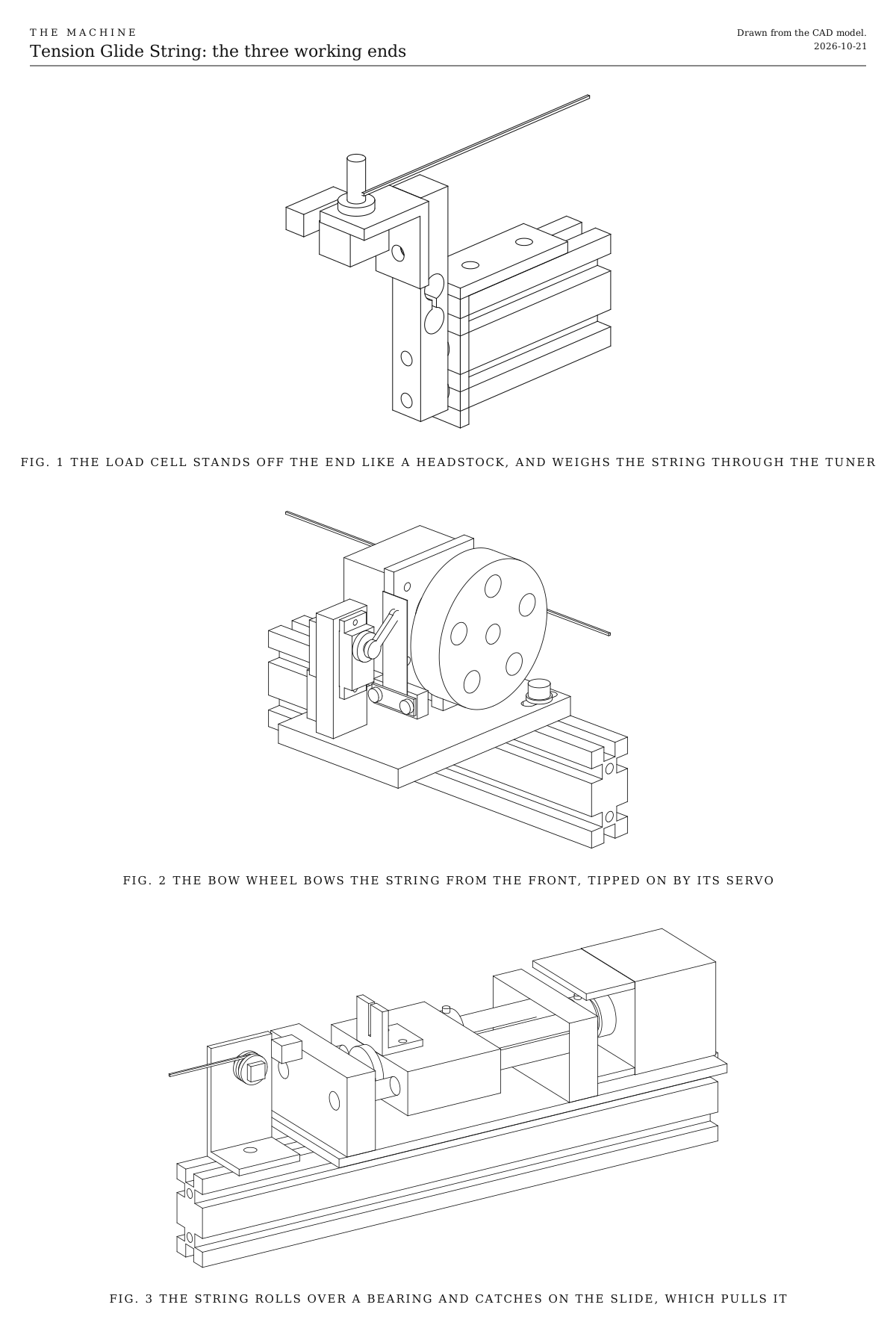
The three working ends. The load cell standing off the end with the tuner on top of it, the Bow Wheel beside the string, and the slide that pulls the string. Drawn from the CAD model.
Fig. 1The three working ends. The load cell standing off the end with the tuner on top of it, the Bow Wheel beside the string, and the slide that pulls the string. Drawn from the CAD model.

How it works

  • One guitar string runs 520 mm from a tuner to a V-groove bearing, about 46 mm above a 700 mm aluminum extrusion. It’s Lapless Steel’s string, tuned to Lapless Steel’s D3.
  • Nothing slides along the string. Lapless Steel changes a string’s length; this changes how hard it’s pulled. Past the bearing, the string’s ball end catches on the carriage of a bought lead-screw slide. Turning the screw pulls the string tighter or lets it down, and the note glides with it.
  • A small pull makes a big glide. Pitch goes with the square root of the pull, so a fifth takes 2.25 times the pull. The whole fifth, D3 down to G2, is about 1.4 mm of travel, less than a turn of the screw.
  • The motor only ever lets the string down and pulls it back. The top note is the string’s normal tuning, at about 100 N, and the slide glides it down from there to about 45 N. Three things keep it from pulling harder. The slide’s motor is turned down so it stalls first, the load cell reads the pull and the firmware won’t go past the top note, and a collar on the slide’s rod blocks the carriage there.
  • The Bow Wheel bows the string, like a hurdy-gurdy. It’s an element of its own, on top of the extrusion in front of the string, with its wheel 55 mm short of the bearing. Its servo tips the rosined wheel onto the string through a soft steel blade, so the pressure stays even while the pull changes, and lifts it clear on the beat. It plays on its own number, alongside the glide.
  • A load cell weighs the pull. It stands off the end of the extrusion like a headstock, with the tuner on top of it, so it feels the string’s whole pull. The pitch follows from the pull, so the firmware can glide to a note and hold it there while the string settles and the room warms.
  • A magnetic guitar pickup under the string, near the tuner end and away from both motors, feeds straight into the console.
  • An ESP32 drives the slide’s motor and reads the load cell. Running from the shared battery, it can join the wireless system.

Notes

  • This is a first design, drawn but not yet built. The 3D model and the files show the version we started with. Bought parts vary, so check your slide, load cell and tuner against the numbers in the CAD script before drilling.
  • The pulls and the 1.4 mm of travel are worked out from the string’s size, not yet measured. A test build will give the real figures.
  • Costs in the ingredients are rough estimates for budgeting, not checked prices.
  • Firmware comes with the broadcast control system. For a first test, any stepper example sketch and the HX711 library’s example will do.

Parts

Ingredients

KindPartQtySourceEach
FabricatedThe Bow Wheel, built from its recipe, electronics and allYour choice: see What sounds the stringIt has its own ESP32, battery adapter and stop button, and plays on its own number, so nothing of it is wired to the Tension Glide.1Link$90.00
FabricatedAluminum angle, 50 x 50 x 4 mm, 20 mm wide, hooked over the tuner endDrill two 5.5 mm holes in each leg. The pair in the top leg go over the top slot; the pair in the hanging leg are 15 mm apart, for the load cell.1·$3.00
FabricatedAluminum angle, 30 x 30 x 4 mm, 20 mm wide, the tuner's shelfDrill one 10 mm hole for the tuner and two 5.5 mm holes 15 mm apart for the load cell.1·$2.00
FabricatedAluminum angle, 50 x 25 x 3 mm, 30 mm long, for the saddleOne 5.5 mm hole in the short leg for the top slot, and one 4.5 mm hole in the tall leg, about 40 mm up, for the bearing's screw.1·$2.00
FabricatedAluminum angle, 20 x 20 x 3 mm, 20 mm wide, the string anchorTwo holes for screws into the carriage, and a slot 1.5 mm wide sawn down the middle of the upright leg, narrower than the string's ball end.1·$1.00
BoughtV-slot aluminum extrusion, 20 x 40 mm, 700 mmAnything from about 650 mm up works; see Variations.1·$18.00
BoughtV-slot extrusion, 20 x 20 mm, 140 mm long, with two corner brackets, as a foot2·$4.00
BoughtLead-screw linear stage, T8 screw with a 2 mm lead, 50 mm of travel, with its NEMA 17 motorAsk for the 2 mm lead, a single-start T8x2. With the common 8 mm lead the string can pull the screw round, so the motor would have to hold it all the time and hum into the pickup. Ours is drawn about 190 mm long with its motor; check yours against the CAD script.1·$45.00
BoughtShaft collar for an 8 mm rod, the stop collar1·$1.00
BoughtV-groove bearing, 624VV (4 x 13 x 6 mm), with an M4 x 30 screw, a nut and a 4 mm spacerThe saddle. The string rolls over it as it stretches, where a fixed saddle would let it catch and step.1·$2.00
BoughtBar load cell, 20 kg, with an HX711 boardYour choice: see How it knows the pitchThe common 80 x 12.7 x 12.7 mm aluminum bar, with M5 threaded holes 15 mm apart at each end. 20 kg is about twice the top note's pull.1·$8.00
BoughtSealed guitar tuners for a 10 mm hole, pack of 6 (3 left, 3 right)The same pack as Lapless Steel's. One is used; either hand works.1·$9.00
BoughtElectric guitar string, wound .036Your choice: see The stringTuned to D3 on 520 mm, it pulls about 100 N, the same as on Lapless Steel.1·$2.00
BoughtFret wrap, or a strip of feltMutes the short length of string behind the saddle.1·$3.00
BoughtSingle-coil guitar pickupYour choice: see The pickupAny Strat-style single coil. It lies along the string, its row of poles 2 to 4 mm under it.1·$15.00
BoughtM3 standoffs, 25 mm, with M3 screws and T-nuts, under the pickup2·$0.50
BoughtMono jack, 6.35 mm, and shielded cableThe pickup's way out. A plug-in wireless guitar transmitter in the jack keeps the element cable-free.1·$3.00
BoughtM5 screws and T-nuts for 20 mm V-slot14·$0.30
BoughtM3 x 10 screws, for the string anchor2·$0.10
BoughtESP32 development board1·$6.00
BoughtTMC2209 stepper driver, for the slide's motorQuiet, which matters with a pickup a few centimeters away.1·$6.00
Bought5 V buck converter, 3 A1·$3.00
BoughtBattery adapter for the shared power-tool platformThe slide's driver runs from the battery, through the fuse, the stop button and the relay.1·$15.00
BoughtThe listener parts every element carries, as on the Control pageA blade fuse holder and 2 A fuse, a latching stop button with a spare contact, the status light, the number switches and their resistors. The stop switch under Choices has a plain two-pole switch in place of the stop button.1Link$12.00
BoughtMomentary push button, normally open, for the test buttonA short press plays each note once, and a long press relearns what the element can by itself. Any small panel button that closes while it's pressed will do.1·$1.00
BoughtRelay module, 5 V, high-level trigger, contacts rated 10 AThe switch the slide motor's power goes through. It stands in for the MOSFET the Control page also allows, because a MOSFET module switches the ground side, which would leave the stepper driver grounded only through the ESP32.1·$2.00
BoughtResistor, 10 kΩHolds the relay off while the ESP32 starts.1·$0.10
BoughtElectrolytic capacitor, 100 µF, 35 VAcross the driver's motor supply, to soak up the spikes the motor sends back.1·$1.00
BoughtSmall project box, about 120 x 40 x 40 mm, for the electronicsYour choice: see The electronics1·$6.00
Total$269.50

Tools

  • Drill, with 4.5, 5.5 and 10 mm bits
  • Hacksaw or a thin file, for the anchor's slot
  • Hex keys, 2, 2.5, 3 and 4 mm
  • Small screwdriver
  • Soldering iron, for the pickup, the jack and the load cell's leads
  • Multimeter
  • A luggage scale, to check how hard the slide can pull
  • Safety glasses, while bringing the string up to pitch
  • Clip-on tuner
  • An amp, or a cable to the console, to listen

Choices

Decisions that are yours to make. Where we started is the version in the 3D model and the ingredients: a starting point, not the right answer.

What sounds the string

Which of the string elements makes it sound?

The Bow WheelWhere we started

SoundThe hurdy-gurdy sound, a buzzing, reedy drone that glides with the pull

An element of its own, on top of the extrusion in front of the string. Its servo brings the wheel in and out on the beat, and its blade keeps the pressure even across a glide. Its page has the choice of rim.

The E-Bow

SoundA pure, endless note that swells in from nothing, so every glide comes out smooth

An element of its own, clamped behind the extrusion between the pickup and the Bow Wheel. Two coils hold the string ringing without touching it. The Bow Wheel lifts clear by itself, so both can stay fitted and take turns.

The Motor Pick

SoundPlucked, so each glide bends a note as it rings away, like a pedal steel

An element of its own, near the saddle in place of the Bow Wheel. The note fades as it glides, so long glides want a fresh pluck.

Hurdy-gurdy players wind a few wisps of cotton round the string where the wheel touches. It rounds off the rasp.

The string

Which string, and which note at the top?

Wound .036, tuned to D3 at the topWhere we started

SoundFull and raspy when bowed; the winding gives it grit

Cheap, and sold singly at any guitar shop. It's Lapless Steel's string at Lapless Steel's tuning.

Flatwound .036

SoundSmoother and darker, closer to a cello

Costs more, and is mostly sold in sets. Its smooth surface needs a little more rosin.

Plain steel, .017 to .024, tuned higher

SoundBright and thin, like a violin's top string

The whole glide moves up into the treble. Plain strings break at a lower pull, so its top note must be its usual one.

Whatever the string, put its top note at the pull a guitar string tension chart gives for its usual tuning, about 80 to 100 N. Glide down from there, never above it.

How far it glides

How far below the top note does it go?

A fifth, D3 down to G2Where we started

SoundThe full swoop

The pull drops from 100 N to 45 N. Near the bottom the string softens, so the wheel wants a gentler touch there.

A fourth, D3 down to A2

SoundA shorter swoop, firm all the way

The pull stays above 56 N, so it bows evenly across the whole range.

A tone or two

SoundMicrotonal drift, bends and wide vibrato around one note

The string stays near full pull and sounds its best. The slide barely moves.

Past a fifth the string goes floppy. An octave would take the pull down to a quarter, where the string wobbles in pitch as it's bowed and the wheel can't hold it.

How it knows the pitch

What tells the firmware where the note is?

A load cell under the tunerWhere we started

SoundGlides land in tune and stay there

About $8 with its board. It reads the pull itself, so it keeps up as a new string stretches and the room warms, and it lets the firmware refuse to pull past the top note.

A table of positions

SoundIn tune when you measure it, drifting a few cents as the string settles

Nothing to add. Measure the slide's position for a few notes with a clip-on tuner, as on Lapless Steel, and measure again before a show.

Listening through the pickup

SoundThe most exact, even as the string wears

A small preamp from the pickup to one of the ESP32's inputs, and the hardest firmware of the three

The pickup

How does it hear the string?

Magnetic single coilWhere we started

SoundClear, with the bowed buzz and little of the wheel's scrape

About $15, and the same pickup as Lapless Steel's. It ignores the wheel's rasp, but hums near the motors' wires.

Piezo disc under the saddle's angle

SoundBrighter and more acoustic, with the wheel's scrape and rasp in it

About $1. It also hears both motors through the frame.

The stop switch

What cuts the slide motor's power at the element?

Latching emergency-stop button, with a spare contactWhere we started

The red mushroom head anyone nearby knows to hit. It stays down until it's twisted to release, so the element can't start again by accident. Its main contact cuts the power and its spare contact tells the ESP32. About $8.

Two-pole power switch, a rocker or a toggle

Smaller, plainer and cheaper, about $2. One pole cuts the power and the other tells the ESP32, so it does the same job. It doesn't read as a stop to someone who doesn't know the Machine, and it switches back on as easily as off. Rate its contacts above what the element draws, as the button's are.

Keep the second pole either way. It tells the ESP32 the power was cut, so it resets itself when the power comes back, as after a stop from the Bridge. Either way the relay stays, since it's how a stop from the Bridge reaches the element when no one is at it. A two-pole switch wires as the button does: one pole in place of the main contact, from 11 to 12, and the other in place of the spare contact, from 13 to 14.

Assembly

  1. 1

    Bolt the two short pieces of 20 x 20 extrusion across the underside as feet, one about 40 mm in from each end, with corner brackets, reaching further out in front than behind.

    CheckIt stands without rocking, and doesn't tip when you press down on the front.

  2. 2

    Drill the 50 x 50 angle and bolt it over the tuner end, one leg on top with two M5 screws into T-nuts in the top slot and the other hanging down past the end, about 6 mm clear of it.

    CheckThe hanging leg is square to the extrusion, and a screw head fits in the gap behind it.

  3. 3

    Bolt the load cell upright to the hanging leg by its lower end, the end its cable leaves from, with two M5 screws from behind and two washers between the cell and the leg. Turn it so the arrow on its label points along the string, toward the extrusion.

    TrickyOnly ever hold the cell by its end holes. Don't drill it, clamp its middle or let anything rest against it, or it reads wrong. The washers keep its middle clear of the leg.

    CheckNothing touches the cell except at its two ends, and its top is about 40 mm above the extrusion.

  4. 4

    Drill the 30 x 30 angle, stand the tuner in its 10 mm hole with the key toward the back, and bolt the angle to the cell's upper end so the tuner sits on top, level with the top of the cell.

    TrickyThese tuners are made for a guitar headstock 13 to 15 mm thick, and the shelf is 4 mm. If the bushing bottoms out before it grips, stack washers between the shelf and the tuner's body.

    CheckThe tuner's post stands straight up, and turning the key doesn't turn the tuner in its hole.

  5. 5

    Bolt the lead-screw slide along the top at the far end, its motor at the end, with two M5 screws through its base into T-nuts in the top slot.

    TrickyIf none of the base's holes sit over the slot's center line, drill two.

    CheckThe screw lines up over the top slot, and turning the coupler by hand runs the carriage from end to end.

  6. 6

    Saw the anchor's slot down the middle of the small angle's upright leg, stopping 2 mm above its other leg, and screw the angle to the top of the carriage at the end facing the tuner.

    CheckThe string's plain end drops down the slot, and its ball end won't pass through.

  7. 7

    Fit the V-groove bearing to the tall angle on its M4 screw, with the spacer between, and bolt the angle into the top slot 520 mm from the tuner post.

    TrickySight along the extrusion from the tuner end. The front of the tuner post, the bearing's groove and the anchor's slot all have to line up over the top slot, or the string rubs the side of the groove and the glide catches.

    CheckThe bearing spins freely, and the bottom of its groove is level with where the string will leave the tuner post, about 46 mm above the extrusion.

  8. 8

    Build the Bow Wheel from its recipe, up to setting its base on a host.

  9. 9

    Set the Bow Wheel's base on top of the extrusion in front of the string, with the wheel's middle about 55 mm short of the saddle, and fix it loosely with two M5 screws through its slots into the top slot.

    CheckThe base clears the saddle's angle, and the wheel's middle sits level with where the string will run, 46 mm above the extrusion.

  10. 10

    Fit your pickup on its two standoffs in the top slot, about 130 mm from the tuner post, lying along the string with its poles 2 to 4 mm below where the string will run. Solder it to the jack.

    CheckTapped with a screwdriver, the poles come through the amp or the console.

  11. 11

    Mount the electronics, the stop button and the battery adapter on the back face, and wire them as the Wiring tab shows. The Bow Wheel's box and battery go on the back face too, between the Tension Glide's electronics and the slide, wired as its own page shows.

    TrickyKeep the pickup's cable and the load cell's cable apart from the slide's and the Bow Wheel's motor cables, or the pickup hums and the cell's reading jitters.

  12. 12

    With no string on, set how hard the slide can pull: tie a loop of cord from the anchor to a luggage scale hooked on the saddle's angle, drive the carriage away slowly, and turn the slide driver's current down until the motor stalls between 11 and 14 kg.

    TrickyThis is what stops a runaway program from snapping the string. The top note pulls about 10 kg, and a wound .036 breaks well above 20 kg.

    CheckIt stalls in that range three times running.

  13. 13

    Run the carriage to about 15 mm from the slide's end block nearest the tuner, then string it. Drop the string into the anchor's slot so the ball end catches behind, run it over the bearing and past the wheel, and wind it onto the tuner post so it leaves the post's front side. Tune it up to D3 with the tuner.

    TrickyWear safety glasses while it comes up to pitch. If it goes much past D3, stop; something is off.

    CheckThe string sits in the bearing's groove and clears the top of the load cell, and the cell reads about 10 kg.

  14. 14

    Slide the stop collar along the back rod until it touches the carriage's far side, and tighten it.

    CheckTold to pull further, the carriage stalls against the collar and the note doesn't rise.

  15. 15

    Wrap the fret wrap round the short length of string behind the saddle.

    CheckPlucked behind the saddle, it thuds instead of ringing.

  16. 16

    Finish setting up the Bow Wheel as its own page says, with the string at D3. Find its servo's positions, check which way it turns, true and rosin its rim, and set its three points of speed and pressure.

    TrickySet the three points with the string glided to the middle of its range, not at the top. The slacker string at the bottom of a glide wants a lighter touch than the tight one at the top.

  17. 17

    Before any firmware does the gliding, type "try 110 0.45" at the Bow Wheel's console so it bows, then turn the slide's coupler slowly by hand and listen to the note glide. Type "lift" when you're done.

Wiring

The fuse comes first, right after the battery. The ESP32 runs from the 5 V converter. The slide motor's power goes through the stop button and then the relay, so either one cuts it. The load cell's board runs from the ESP32's 3.3 V. The Bow Wheel has its own ESP32, battery and wiring, on its own page. The pickup is wired on its own, straight to its jack. The status light, the number switches and the battery reading are wired the same way on every element, so they're on the Control page, not here.

Wiring · Tension Glide String
PowerSignalMotorGround, all joinedPins drawn faint are left empty.

Wire list

  1. Battery adapter, +

    Fuse, 2 A, in

    PowerRed, 16 AWG

    As short as the adapter allows. Nothing connects ahead of the fuse.

  2. Fuse, 2 A, out

    5 V converter, IN+

    PowerRed, 22 AWG

  3. Fuse, 2 A, out

    Stop button, 11

    PowerRed, 18 AWG

  4. Stop button, 12

    Relay module, COM

    PowerRed, 18 AWG

    The stop button's main contact opens when pressed, cutting the slide motor's power itself, so a program that hangs can't ignore it.

  5. Relay module, NO

    TMC2209, slide, VM

    PowerRed, 18 AWG

  6. Capacitor, 100 µF, +

    TMC2209, slide, VM

    PowerThe capacitor's own leg

    Solder its legs straight onto the driver's VM and GND pins. The stripe on its side marks the − leg.

  7. 5 V converter, OUT+

    ESP32 board, 5V

    PowerRed, 22 AWG

    Only once the converter is set to 5 V.

  8. 5 V converter, OUT+

    Relay module, VCC

    PowerRed, 22 AWG

  9. ESP32 board, 3V3

    TMC2209, slide, VDD

    PowerRed, 22 AWG

    The driver's logic runs at the ESP32's 3.3 V, so their signals match.

  10. ESP32 board, 3V3

    HX711 board, VCC

    PowerRed, 22 AWG

    At 3.3 V the board's data matches the ESP32's pins.

  11. Battery adapter, −

    5 V converter, IN−

    GroundBlack, 22 AWG

  12. Battery adapter, −

    TMC2209, slide, GND

    GroundBlack, 18 AWG

    The motor's return. Use the driver's GND pin next to VM.

  13. Capacitor, 100 µF, −

    TMC2209, slide, GND

    GroundThe capacitor's own leg

  14. 5 V converter, OUT−

    ESP32 board, GND

    GroundBlack, 22 AWG

  15. ESP32 board, GND

    TMC2209, slide, GND

    GroundBlack, 22 AWG

    The driver's other GND pin, next to VDD.

  16. Relay module, GND

    ESP32 board, GND

    GroundBlack, 22 AWG

  17. Resistor, 10 kΩ, 2

    ESP32 board, GND

    GroundThe resistor's own leg

  18. Stop button, 14

    ESP32 board, GND

    GroundBlack, 22 AWG

  19. Test button, 2

    ESP32 board, GND

    GroundBlack, 22 AWG

  20. HX711 board, GND

    ESP32 board, GND

    GroundBlack, 22 AWG

  21. ESP32 board, GPIO 25

    TMC2209, slide, STEP

    SignalAny color, 22 AWG

  22. ESP32 board, GPIO 26

    TMC2209, slide, DIR

    SignalAny color, 22 AWG

  23. ESP32 board, GPIO 27

    TMC2209, slide, EN

    SignalAny color, 22 AWG

    Low turns the motor on. The screw holds the string by itself, so the ESP32 switches the slide's motor off whenever the note holds still, and it can't hum into the pickup.

  24. ESP32 board, GPIO 33

    Relay module, IN

    SignalAny color, 22 AWG

  25. Resistor, 10 kΩ, 1

    Relay module, IN

    SignalThe resistor's own leg

    Holds the relay off while the ESP32 starts, when its pins float.

  26. Stop button, 13

    ESP32 board, GPIO 13

    SignalAny color, 22 AWG

    The stop button's spare contact, so the ESP32 knows it's been pressed.

  27. Test button, 1

    ESP32 board, GPIO 15

    SignalAny color, 22 AWG

    The test button. The ESP32's own pull-up holds the pin high until it's pressed. The board reads GPIO 15 as it starts, but only to choose whether to print, so holding the button then does no harm.

  28. ESP32 board, GPIO 23

    HX711 board, SCK

    SignalAny color, 22 AWG

  29. ESP32 board, GPIO 32

    HX711 board, DT

    SignalAny color, 22 AWG

    DT is the board's data output; the ESP32 reads the pull on GPIO 32.

  30. HX711 board, E+

    Load cell, red

    SignalThe load cell's red lead

  31. HX711 board, E−

    Load cell, black

    SignalThe load cell's black lead

  32. HX711 board, A−

    Load cell, white

    SignalThe load cell's white lead

  33. HX711 board, A+

    Load cell, green

    SignalThe load cell's green lead

    If the reading falls as the string tightens, swap white and green.

  34. TMC2209, slide, 1A

    Slide's stepper, A1

    MotorThe motor's own cable

    1A and 1B go to one coil, 2A and 2B to the other.

  35. TMC2209, slide, 1B

    Slide's stepper, A2

    MotorThe motor's own cable

  36. TMC2209, slide, 2A

    Slide's stepper, B1

    MotorThe motor's own cable

  37. TMC2209, slide, 2B

    Slide's stepper, B2

    MotorThe motor's own cable

  38. Pickup, hot

    Output jack, tip

    SignalShielded cable, its center core

    On most single coils the white or yellow lead is hot and the black one is ground. Check yours.

  39. Pickup, ground

    Output jack, sleeve

    SignalShielded cable, its braid

    The pickup's ground stays with the jack, apart from the electronics' ground.

  40. String and tuner, tuner shelf

    Output jack, sleeve

    SignalAny color, 22 AWG, from a screw on the tuner's shelf

    Grounds the string through the tuner, which cuts hum when a hand or the console's cable is near. The shelf stays still, where the anchor moves with the slide.

Get these right

Set the converter first
Most 5 V converters come set higher. Turn its screw with the battery in and a multimeter on its output until it reads 5.0 V, and only then connect the ESP32. More than about 6 V destroys the board.
Turn the slide's current down
On its fine screw, the slide's motor can pull over 30 kg, enough to snap the string. With its driver's current turned down, the motor stalls first. Set it with a luggage scale as the Assembly tab says, so it stalls between 11 and 14 kg, and check again whenever you change the driver or the motor.
The load cell's leads
Most cells use red and black for power and white and green for the reading. If yours are colored differently, its listing says which is which. Run its cable apart from the motors' cables, or the reading jitters.
Finding the motor's coils
Motor wire colors vary by maker. Touch two wires together and turn the shaft by hand; if it suddenly turns stiffly, those two are one coil. If a motor runs the wrong way, swap the two wires of one coil.
Never unplug a motor with power on
Pulling a motor's plug while its driver has power can destroy the driver. Switch off, or press the stop button, first.
Keep the pickup's cable apart
Run the pickup's shielded cable on its own, away from the motors' cables and the drivers. A stepper's current pulses are the loudest hum a magnetic pickup can catch.

Mounting

Everything fixes to the V-slot with T-nuts and screws, so any part can slide to a new place or come off with a hex key. Only the slide's carriage moves, and only by a millimeter or two while it plays, so nothing wired has to follow it.

The load cell and the tuner
An angle hooks over the tuner end, with two M5 screws into the top slot and its other leg hanging down past the end. The load cell stands on that leg by its lower end, and the tuner's shelf bolts to its upper end. Only the cell holds the tuner, so it feels the string's whole pull.
The pickup
On two M3 standoffs on T-nuts in the top slot, about 130 mm from the tuner post. It slides along to change the tone; further from the post is warmer.
The Bow Wheel
Its base sits on top in front of the string, two M5 screws through its slots into the top slot, with the wheel's middle about 55 mm short of the saddle. Its box, with its stop button on top, and its battery adapter go on the back face between the Tension Glide's electronics and the slide.
The saddle
Its angle bolts into the top slot with one M5 screw, 520 mm from the tuner post. Moving it changes the string's length, and the whole range moves with it.
The slide
Along the top at the far end, with two M5 screws through its base into the top slot. The stop collar on its back rod sets how far it can pull.
The feet
Two short pieces of 20 x 20 extrusion across the underside, reaching forward under the Bow Wheel, with two corner brackets each on the bottom slot.
The electronics
On the back face's lower slot, toward the tuner end, away from the Bow Wheel's motor.
The stop button
In its own housing on the back face near the tuner end, where a hand finds it without reaching past the Bow Wheel.
The battery
The adapter sits on the back face under the slide, on two T-nuts, so the pack slides on and off without moving anything else.
The wires
Clip-in slot covers hold the wires in the back face's lower slot. The load cell's cable comes down from the headstock into the bottom slot with the pickup's cable, apart from the motors' cables.

The electronics

Hidden in a box, or on show?

Closed boxWhere we started

A small project box, bought or printed, on the back face. Tidy, and it keeps the drivers' noise a little further from the pickup, but it hides the electronics.

Open plate

The boards on standoffs on a flat plate on the back face, with the wires dressed along the slot. The electronics become part of the look. It wants neat wiring, and nothing guards it from knocks.

DIN rail

A short length of 35 mm DIN rail on T-nuts, with each board in a snap-on holder. It looks like a control panel, and any board comes off with a flick. The holders add a few dollars.

Whichever you pick, keep the stop button on the outside, where anyone can reach it.

Tuning

Tuning

The test button
A short press glides through its pitches once, low to high. The Bow Wheel has its own test button, so press it too to hear the glide bowed. A long press does nothing here, since its load cell always knows how hard the string is pulled. It works only while the element is resting, with no Bridge in range or with the Bridge holding it silent. While it plays or is stopped, the button does nothing. A stop ends a test at once, and pressing again ends one early. The pull for each note is still set with a clip-on tuner, at the console.
Whistles, crunches, or a pulse once a turn
These are the bowing itself, and the Bow Wheel's Tuning tab says what to listen for and what to change.
Crunchy at the bottom of a glide, thin at the top
The Bow Wheel presses just as hard all through a glide, but the slacker string at the bottom wants a lighter touch than the tight one at the top. Set its points with the string in the middle of the glide, and for a long glide down, send the Bow Wheel a little softer as the note falls.
Glides that step instead of sliding
Something catches as the string stretches. Usually the string is rubbing the side of the bearing's groove, or the bearing doesn't turn freely. Line them up again, or fit a new bearing.
Notes drifting sharp through a show
A new string keeps stretching for days, and a warming room tightens it, because the aluminum grows faster than the steel. The firmware holds a pull rather than a position, so the load cell keeps up. If notes still sit off, measure the pull for a few notes again with a clip-on tuner.
A second note behind the saddle
The short length behind the saddle is ringing. Wrap the fret wrap tighter, or add a second one.
A hum between notes
Move the pickup's cable away from the motors' wires. The screw holds the string by itself, so the firmware can switch the slide's motor off whenever the note holds still, and the Bow Wheel switches its motor off once its wheel has stopped.
Thin, or a short wobbly ring
Thin means the pickup is too far away; raise it. A short, wobbly ring means it's so close its magnet pulls on the string; lower it. Somewhere between 2 and 4 mm.

Variations

A longer or shorter string
Nothing here depends on 520 mm. The extrusion is about 180 mm longer than the string, to make room for the slide. A longer string sits lower for the same pull, about a major third lower on 650 mm, and the slide travels a little further for the same glide.
A lever you can see
Hook the string's end near the pivot of a long arm, like the changer on a pedal steel or a timpani's pedal, and push the arm's far end with the slide. A big, slow swing you can watch makes the same small pull. The pivot carries the string's whole 100 N.
A motor on the tuning key
The fewest parts. Couple a motor to the tuner's key and leave out the slide; about one turn of the key is a fifth. The tuner's gears have play, so small moves and vibrato go soft.
Several strings, gliding into one chord
A row of these, each starting from its own pitch and gliding to a note of one chord, makes a cluster that settles into harmony, like the THX Deep Note. Each string needs its own slide, Bow Wheel and load cell; the tuners come in packs of six.