Skip to content

The Machine · Recipes

Bow Wheel

Design stage

Updated 2026-10-21

A rosined wheel on a small motor, tipped onto a steel string by a servo, so it bows the string like a hurdy-gurdy, on the beat and as hard as each note asks. It sits on any string element and plays on its own number.

Loading the model

Drag to turn · scroll to zoom

Printed

3DThe unit, on a stand-in string. This is the version we started with, on a stand-in for whichever element it's mounted on: a plain length of extrusion with one string, the same one the E-Bow is drawn on. The two printed parts are drawn in orange. Press Play to watch it spin up, tip onto the string, bow softly and then louder, lift, and come back to damp the string. The wheel turns slower than it would, and the string's swing is drawn far bigger and slower than life.

Overview

Cost, roughly
About $90
Printing
About 4 hours
Building
A weekend
Difficulty
Moderate

Anatomy

1
Energy source
A stepper turns a rosined wheel, and its rim drags the string and lets it slip, over and over
2
Control
A servo tips the wheel onto the string through a soft steel blade, pressing harder for louder notes as the wheel turns faster
3
Sounding body
Whichever steel string it's mounted beside; that element's pickup carries the sound
4
Reset
None needed; lifted, the wheel leaves the string free
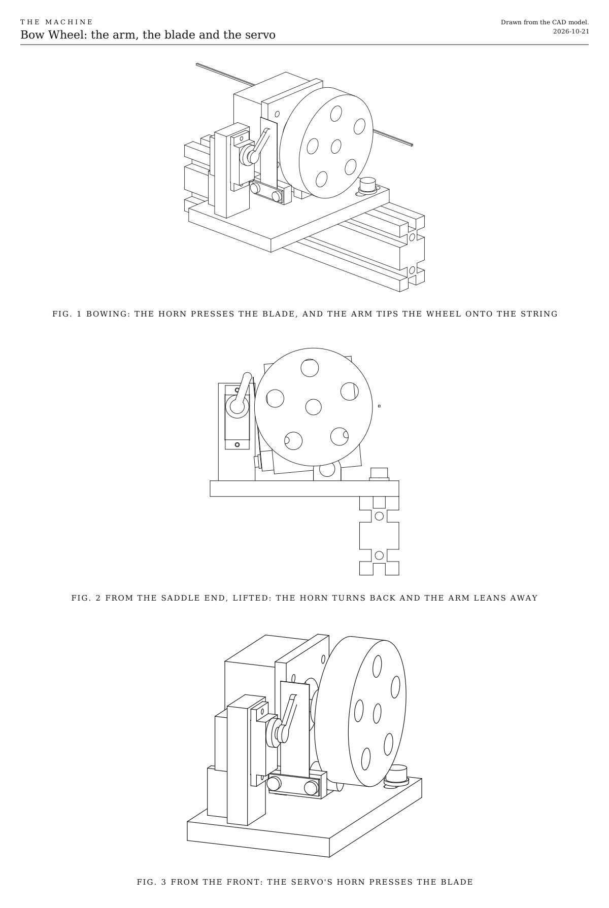
The arm, the blade and the servo. The wheel bowing the string, the unit lifted clear as seen from the saddle end, and the servo's horn pressing the blade. Drawn from the CAD model.
Fig. 1The arm, the blade and the servo. The wheel bowing the string, the unit lifted clear as seen from the saddle end, and the servo's horn pressing the blade. Drawn from the CAD model.

How it works

  • It bows a string that belongs to another element. The Bow Wheel makes no sound of its own. It sits beside the steel string of another element, and that element’s pickup carries the note to the console.
  • A turning rosined wheel bows the string, like a hurdy-gurdy. The rim grips the string and drags it along, until the string snaps back and slips, then grips it again, hundreds of times a second. That’s the same stick and slip a violin’s bow makes, and it’s what keeps the note going for as long as the wheel turns.
  • A servo tips the wheel onto the string. The motor hangs on an arm that tips on a hinge running along the string. A micro servo’s horn presses a thin steel blade standing up from the arm, and the blade bends like a soft spring before it moves the arm. The further the horn turns, the more the blade bends and the harder the wheel presses. Turned back, the horn lets the arm lean away by its own weight, and the wheel comes clear.
  • The soft blade keeps the pressure even. A tuned string is stiff sideways, so a wheel held at a fixed place presses much harder for every fraction of a millimeter the string or the wheel wanders. Through the blade, the wheel presses with about the same force whatever the string does, even while the Tension Glide String glides its pitch.
  • Louder means faster and harder together. A bowed string only speaks inside a window of pressure, and the window rises with the rim’s speed. So each note’s loudness sets both how fast the wheel turns and how hard it presses, from three points set by ear.
  • Notes start on the beat. The wheel spins up while it’s still clear of the string. The servo starts early, by however long it takes to bring the wheel in and for the string to speak, so the note sounds on its beat.
  • It’s an element of its own. It has its own ESP32 listening to Control on its own number, its own battery, and the stop button and relay every element has. It can bow while its host plays its own notes, or play over a host that’s resting.

What its notes do

  • 0, bow. The wheel meets the string on this note and keeps bowing. Loudness sets its speed and pressure; sent again while it bows, the note swells or fades to the new loudness.
  • 1, lift. The wheel leaves the string on this note, and the string rings on.
  • 2, stroke. The wheel meets the string on this note and leaves it half a beat later.
  • 3, damp. The still wheel comes back and rests on the string on this note, to stop it ringing, then lifts again.

On its hosts

  • The Tension Glide String is bowed by a wheel already. The Bow Wheel takes the place of that wheel and its printed mount, at the same spot about a tenth of the string’s length short of its saddle. Its box and battery go on the Tension Glide’s back face, between the Tension Glide’s own electronics and its slide. With the blade’s even pressure, the top of a glide no longer comes out louder and harsher than the bottom.
  • Lapless Steel could take one too. Its string runs only about 23 mm above its bar, too low for the middle of a 60 mm wheel, so it wants the smaller wheel from the Variations.

Notes

  • This is a first design, drawn but not yet built. The 3D model and the files show the version we started with, on a stand-in host. Bought parts vary, so check your motor and servo against the numbers in the CAD script before printing.
  • The speeds, the pressures and the blade’s stiffness are worked out from how bowed strings behave and from the blade’s size, not yet measured on this build.
  • Costs in the ingredients are rough estimates for budgeting, not checked prices.
  • The firmware in the downloads is a first version. It compiles, and its timing is tested against a simulated wheel and servo, but it hasn’t yet run on a built element. It listens for Control, the one broadcast signal every element hears.

References

  • The hurdy-gurdy bows its strings with a rosined wheel turned by a crank, the way this unit does with a motor.
  • John Schelleng’s 1973 paper “The bowed string and the player” mapped the window of bow pressure inside which a bowed string speaks cleanly, and showed how it rises with the bow’s speed and narrows nearer the bridge.

Parts

Ingredients

KindPartQtySourceEachFile
PrintedBase, sits on the host's bar and holds the hinge and the servo1··STL
PrintedArm, carries the motor, tips on the hinge and holds the blade1··STL
BoughtPancake NEMA 17 stepper motor, 42 mm square and about 23 mm longYour choice: see The motorSold as 17HS4023 or similar. A standard 40 mm NEMA 17 works too, but nearly doubles the weight the servo tips.1·$10.00
BoughtWooden wheel, 60 mm across and about 15 mm wideYour choice: see The rimCraft and toy wheels work. Beech or maple holds rosin best.1·$3.00
BoughtRigid flange coupling for a 5 mm shaft, with four small wood screws1·$3.00
BoughtRosin, a cake for violin or celloYour choice: see The rim1·$5.00
BoughtMicro servo, MG90S, with its horns and screwsYour choice: see Getting on and off the stringMetal gears. The single-arm horn presses the blade.1·$4.00
BoughtFeeler gauge set, for one leaf of 0.25 mm, the bladeYour choice: see Getting on and off the stringThe blade is the soft spring. A 0.3 mm leaf is stiffer; a longer free length is softer.1·$5.00
BoughtSmall flat steel mending plate, about 25 mm long, with two M3 x 12 screws, the blade's clamp1·$1.00
BoughtM4 x 30 screw with a nylon-insert nut and two washers, the hinge1·$0.30
BoughtM3 x 10 screws, for the motor4·$0.10
BoughtM5 x 12 screws, washers and T-nuts for 20 mm V-slotTwo for the base, and the rest for the box, the battery adapter and the stop button.8·$0.30
BoughtESP32-S3 development board1·$8.00
BoughtTMC2209 stepper driverQuiet, which matters with a pickup a few centimeters away.1·$3.00
BoughtElectrolytic capacitor, 100 µF, 35 VAcross the driver's motor supply, to soak up the spikes the motor sends back.1·$0.50
Bought5 V buck converter, 3 A1·$3.00
BoughtAdjustable buck converter, 3 A, set to 6 V for the servo1·$3.00
BoughtElectrolytic capacitor, 470 µF, 25 VOn the 6 V converter's output, for the jump in current as the servo starts.1·$0.50
BoughtRelay module, 5 V, high-level trigger, contacts rated 10 AThe switch the motor's and the servo's power go through.1·$2.00
BoughtResistor, 10 kΩHolds the relay off while the ESP32 starts.1·$0.10
BoughtBattery adapter for the shared power-tool platform1·$15.00
BoughtThe listener parts every element carries, as on the Control pageA blade fuse holder and 2 A fuse, a latching stop button with a spare contact, the status light, the number switches and their resistors. The stop switch under Choices has a plain two-pole switch in place of the stop button.1Link$12.00
BoughtMomentary push button, normally open, for the test buttonA short press plays each note once. Any small panel button that closes while it's pressed will do.1·$1.00
BoughtCable, four cores for the motor and three for the servo, about 40 cm of eachFrom the box on the host's back face round to the unit in front.1·$2.00
BoughtSmall project box, about 75 x 40 x 36 mm, for the electronicsYour choice: see The electronics1·$6.00
Total$90.20

Tools

  • 3D printer, PETG or PLA
  • Hex keys, 2, 2.5, 3 and 4 mm
  • Small screwdriver
  • Tin snips, to cut the blade to length
  • Soldering iron
  • Multimeter, to set the converters
  • Fine sandpaper on a flat block, to true the wheel
  • A strip of paper, to feel when the rim touches the string
  • An amp, or a cable to the console, to listen through the host's pickup
  • A phone that films with sound, to time the notes

Choices

Decisions that are yours to make. Where we started is the version in the 3D model and the ingredients: a starting point, not the right answer.

The rim

What does the string rub against?

Rosined hardwoodWhere we started

SoundThe hurdy-gurdy sound, a reedy, buzzing note with a scratch at the start of each one

Cheap, and the same wheel as the Tension Glide String's. It has to be trued once it's on the motor, and it wants fresh rosin every session.

A rubber O-ring in a groove round the rim

SoundSofter and rounder, with less of the reedy bite, and notes start more readily

Turn a shallow groove in the wooden wheel and stretch the ring into it. It grips with little or no rosin, so it sounds the same all through a show. The ring wears where the string runs and needs replacing now and then.

A leather band, rosined

SoundBreathier and quieter, with gentler starts

A strip of smooth leather glued round the wooden wheel. It takes a while to wear in.

Hurdy-gurdy players wind a few wisps of cotton round the string where the wheel touches. It rounds off the rasp. Try it with any rim.

The motor

What turns the wheel?

A pancake NEMA 17 stepper, with a TMC2209 driverWhere we started

SoundVery quiet, in the driver's quiet mode

It holds its speed however hard the string drags, and it's the driver the other elements use. At about 140 g it's the heaviest of the three for the servo to tip.

A small geared DC motor

SoundA faint gear whine, and its brushes hiss into a magnetic pickup nearby

The lightest and the cheapest. The string's drag slows it, so its speed wanders as the pressure changes, and loud notes sag.

A brushless gimbal motor, with an angle sensor

SoundSilent, and the smoothest at slow speeds

No gears and very little weight. It needs a small driver board of its own and the hardest firmware of the three.

Whichever motor, the wheel turns between about 30 and 250 times a minute. On a 60 mm wheel that's a rim speed of 0.1 to 0.8 m/s, about the range a violinist moves a bow.

Getting on and off the string

What brings the wheel onto the string, and takes it off, on the beat?

A servo, tipping the arm through a steel bladeWhere we started

SoundNotes start and stop cleanly on the beat, and each one can be bowed harder or softer

The servo takes about 50 ms to bring the wheel in, so the firmware starts it that much early. The blade bends like a soft spring, so how far the horn turns sets how hard the wheel presses.

A push solenoid against a spring

SoundQuicker, about 20 ms, but it clicks on every note

The pressure is set once by hand, with no changing it from note to note. Holding the wheel off between notes keeps the solenoid warm.

No lift at all

SoundEvery note starts with a scratch as the wheel spins up from still

The fewest parts. The wheel always rests on the string, and starting or stopping the motor starts or stops the note, as the Tension Glide String's own wheel does. The still wheel mutes the string, so it can't share a string with a pick or the E-Bow.

Pressure and loudness

What makes a note louder?

Speed and pressure togetherWhere we started

SoundThe widest range, from a whisper to a full rasp, and every note speaks cleanly

Loudness sets the wheel's speed, and the servo presses harder to match. You set three points by ear while tuning, for soft, middle and loud.

Speed only, with the pressure set once

SoundA narrower range; soft notes crunch, or loud ones whistle, at the ends

Simpler to tune, with one servo position for every note.

Pressure only, at one speed

SoundBarely louder or softer. The tone changes instead, from airy to gritty

The simplest of all. Fine for a drone.

A bowed string only speaks inside a window of pressure. Too light and it whistles or jumps to a higher note; too heavy and it crunches. The faster the rim moves, the louder the note and the higher the window, which is why the pressure has to rise with the speed.

Where along the string

How far from the string's end does the wheel bow it?

About a tenth of the string's length from the bridge or saddleWhere we started

SoundThe full, reedy sound of a hurdy-gurdy

Speaks easily across a wide range of pressures.

About a sixth of the way along

SoundSweeter, rounder and softer

Needs the least pressure, and the window for a clean note is widest here.

Close in, a fifteenth of the way or less

SoundBright, hard and loud, nearer a sul ponticello violin

The window narrows. It needs more pressure and a steadier hand with the three points.

The stop switch

What cuts the motor's and the servo's power at the element?

Latching emergency-stop button, with a spare contactWhere we started

The red mushroom head anyone nearby knows to hit. It stays down until it's twisted to release, so the element can't start again by accident. Its main contact cuts the power and its spare contact tells the ESP32. About $8.

Two-pole power switch, a rocker or a toggle

Smaller, plainer and cheaper, about $2. One pole cuts the power and the other tells the ESP32, so it does the same job. It doesn't read as a stop to someone who doesn't know the Machine, and it switches back on as easily as off. Rate its contacts above what the element draws, as the button's are.

Keep the second pole either way. It tells the ESP32 the power was cut, so it starts again lifted and still when the power comes back, as after a stop from the Bridge. Either way the relay stays, since it's how a stop from the Bridge reaches the element when no one is at it. A two-pole switch wires as the button does: one pole in place of the main contact, from 11 to 12, and the other in place of the spare contact, from 13 to 14.

Print

Material
PETG
Layers
0.2 mm
Walls
4
Infill
40%

There are two printed parts, and neither needs supports. PETG holds its shape in a warm room; PLA is fine for a first try.

The printed parts

  • Base, sits on the host's bar and holds the hinge and the servo

    Which way up
    Flat on its underside
    Supports
    None
    Time
    About 3 hours

    The servo's case slides through the tower's window and its two tabs screw to the tower's face with the servo's own screws. The two slots across the base let it slide 6 mm toward the string or away.

    STL ↓
  • Arm, carries the motor, tips on the hinge and holds the blade

    Which way up
    On its motor's side, which is flat
    Supports
    None
    Time
    About 1 hour

    The motor's raised ring fits the 22 mm hole. The two small holes in the pad take the blade clamp's M3 screws, which cut their own thread.

    STL ↓

Assembly

  1. 1

    Push the servo's case through the tower's window from the back, its shaft near the top and pointing toward the end of the base where the wheel will be, and screw its two tabs to the tower's face with its own screws.

    CheckThe servo's shaft sits near the top of the window, level with the ears' end.

  2. 2

    Screw the motor to the arm's flat side, its raised ring in the big hole, with four M3 screws from the other side. Fit the flange coupling on its shaft and screw the wheel to the flange.

    TrickyCenter the wheel on the flange as well as you can. A wheel that wobbles makes the note pulse once a turn; a later step trues it.

  3. 3

    Hang the arm between the base's two ears on the M4 screw, a washer each side of its lug, and tighten the nylon-insert nut until the arm swings freely with no play.

    TrickyAny play in the hinge lets the wheel chatter on the string. Snug the nut until the arm only just swings freely, and no further.

    CheckTipped by hand it swings without a knock, and let go it leans forward toward the servo by its own weight.

  4. 4

    Take the 0.25 mm leaf from the feeler gauge set, cut it to about 50 mm, and clamp it upright against the front of the arm's pad under the mending plate, with its two M3 screws.

    CheckIt stands straight up, clear of the arm above the pad, and doesn't move in the clamp.

  5. 5

    Find a clear stretch of the host's bar, about 65 mm long, about a tenth of the string's length from its bridge or saddle, or wherever your choice put it. Set the base on top, reaching out in front of the string, and fix it loosely with two M5 screws through its slots into T-nuts in the top slot.

    TrickySome elements keep their saddle, pickup or slide in the top slot. Keep the motor as far from a magnetic pickup as the string allows, or the pickup hears it.

    CheckThe wheel's middle sits level with the string. If the string runs higher, pack the base up with washers under it; if it runs lower than the wheel's middle can go, the unit wants a post (see Mounting).

  6. 6

    Mount the electronics box, the battery adapter and the stop button on the host's back face behind the unit, and wire them as the Wiring tab shows. Run the motor's and the servo's cables round to the unit.

    TrickyRun the motor's cable apart from the host's pickup cable. A stepper's current pulses are the loudest hum a magnetic pickup can catch.

  7. 7

    Set both converters, 5 V and 6 V, with a multimeter, before anything is connected to them.

  8. 8

    Load the firmware from the downloads and open its console. Type "servo 1500" to hold the servo in the middle of its turn. Push the horn onto the shaft pointing up and leaning a little toward the string, and fit its screw.

    CheckThe horn's tip rests against the blade, about two thirds of the way up it.

  9. 9

    Slide the base toward the string until the rim just touches it, with the arm standing straight up, and tighten the base's two screws.

  10. 10

    Find the servo's three positions with the console. Type "servo" with pulses either side of 1500 until the horn just tips the wheel onto the string without bending the blade, and type "set touch" with that pulse. Find where the rim sits about 3 mm clear and type "set lift"; then where the blade bends about 4 mm, the hardest you'll want it to press, and type "set full". Type "save".

    CheckAt touch, a strip of paper between the rim and the string is just pinched. At lift it slides out freely.

  11. 11

    Type "spin 60" with the wheel lifted, and watch which way the rim runs past the string. It should run down. If it runs up, type "flip", then "save".

    TrickyRunning up past the string, the string's drag pulls the wheel in harder, and it grabs and crunches. Running down, the drag eases it off, which keeps it steady.

  12. 12

    With the wheel spinning slowly and lifted, true its rim with fine sandpaper on a flat block resting on the base.

    TrickyKeep the block clear of the string, and fingers clear of the hinge and the horn.

    CheckA pencil held just off the rim sees the same gap all the way round.

  13. 13

    Rosin the rim well. Type "try 110 0.45" to bow at 110 turns a minute and a little under half pressure, and listen, then "lift".

    TrickyA new wheel takes a lot of rosin before it grips. Keep rosining until it does.

    CheckThe string speaks within a moment of the wheel touching it.

  14. 14

    Set the three points by ear. With "try", find a speed and pressure for a soft note that speaks without whistling, and type "set soft" with them; then a full, clean middle note for "set middle", and a loud one that rasps without crunching for "set loud". Type "save".

    TrickyThe right pressure is a narrow band at each speed. The Tuning tab says what to listen for.

  15. 15

    Film it with sound while you type "play 0", which bows a second from now, then "play 1" to lift. Measure from the horn starting to move to the note sounding, and type "set lead" with it in milliseconds, then "save".

Wiring

The fuse comes first, right after the battery. The ESP32 runs from the 5 V converter. The motor's driver and the servo's 6 V converter take their power through the stop button and then the relay, so either one cuts both. The driver's logic runs from the ESP32's 3.3 V. The status light, the number switches and the battery reading are wired the same way on every element, so they're on the Control page, not here.

Wiring · Bow Wheel
PowerSignalMotorGround, all joinedPins drawn faint are left empty.

Wire list

  1. Battery adapter, +

    Fuse, 2 A, in

    PowerRed, 16 AWG

    As short as the adapter allows. Nothing connects ahead of the fuse.

  2. Fuse, 2 A, out

    5 V converter, IN+

    PowerRed, 22 AWG

  3. Fuse, 2 A, out

    Stop button, 11

    PowerRed, 18 AWG

  4. Stop button, 12

    Relay module, COM

    PowerRed, 18 AWG

    The stop button's main contact opens when pressed, cutting the motor's and the servo's power itself, so a program that hangs can't ignore it.

  5. Relay module, NO

    TMC2209 stepper driver, VM

    PowerRed, 18 AWG

  6. Relay module, NO

    6 V converter, servo, IN+

    PowerRed, 20 AWG

  7. Capacitor, 100 µF, +

    TMC2209 stepper driver, VM

    PowerThe capacitor's own leg

    Solder its legs straight onto the driver's VM and GND pins. The stripe on its side marks the − leg.

  8. 5 V converter, OUT+

    ESP32-S3 board, 5V

    PowerRed, 22 AWG

    Only once the converter is set to 5 V.

  9. 5 V converter, OUT+

    Relay module, VCC

    PowerRed, 22 AWG

  10. ESP32-S3 board, 3V3

    TMC2209 stepper driver, VDD

    PowerRed, 22 AWG

    The driver's logic runs at the ESP32's 3.3 V, so their signals match.

  11. 6 V converter, servo, OUT+

    Servo, MG90S, red +

    PowerRed, 22 AWG

    Only once the converter is set to 6 V.

  12. Capacitor, 470 µF, +

    6 V converter, servo, OUT+

    PowerThe capacitor's own leg

    Solder its legs straight onto the converter's output terminals.

  13. Battery adapter, −

    5 V converter, IN−

    GroundBlack, 22 AWG

  14. Battery adapter, −

    TMC2209 stepper driver, GND

    GroundBlack, 18 AWG

    The motor's return. Use the driver's GND pin next to VM.

  15. Battery adapter, −

    6 V converter, servo, IN−

    GroundBlack, 20 AWG

  16. Capacitor, 100 µF, −

    TMC2209 stepper driver, GND

    GroundThe capacitor's own leg

  17. 5 V converter, OUT−

    ESP32-S3 board, GND

    GroundBlack, 22 AWG

  18. ESP32-S3 board, GND

    TMC2209 stepper driver, GND

    GroundBlack, 22 AWG

    The driver's other GND pin, next to VDD.

  19. 6 V converter, servo, OUT−

    Servo, MG90S, brown −

    GroundBlack, 22 AWG

  20. Capacitor, 470 µF, −

    6 V converter, servo, OUT−

    GroundThe capacitor's own leg

  21. 6 V converter, servo, OUT−

    ESP32-S3 board, GND

    GroundBlack, 22 AWG

    So the servo's signal and the ESP32 share a ground.

  22. Relay module, GND

    ESP32-S3 board, GND

    GroundBlack, 22 AWG

  23. Resistor, 10 kΩ, 2

    ESP32-S3 board, GND

    GroundThe resistor's own leg

  24. Stop button, 14

    ESP32-S3 board, GND

    GroundBlack, 22 AWG

  25. Test button, 2

    ESP32-S3 board, GND

    GroundBlack, 22 AWG

  26. ESP32-S3 board, GPIO 16

    TMC2209 stepper driver, STEP

    SignalAny color, 22 AWG

  27. ESP32-S3 board, GPIO 17

    TMC2209 stepper driver, DIR

    SignalAny color, 22 AWG

  28. ESP32-S3 board, GPIO 18

    TMC2209 stepper driver, EN

    SignalAny color, 22 AWG

    Low turns the motor on. The ESP32 switches it off once the wheel has stopped, so it can't hum into the host's pickup.

  29. ESP32-S3 board, GPIO 38

    Servo, MG90S, orange signal

    SignalAny color, 22 AWG

  30. ESP32-S3 board, GPIO 5

    Relay module, IN

    SignalAny color, 22 AWG

    High gives the motor and the servo their power.

  31. Resistor, 10 kΩ, 1

    Relay module, IN

    SignalThe resistor's own leg

    Holds the relay off while the ESP32 starts, when its pins float.

  32. Stop button, 13

    ESP32-S3 board, GPIO 4

    SignalAny color, 22 AWG

    The stop button's spare contact, so the ESP32 knows it's been pressed.

  33. Test button, 1

    ESP32-S3 board, GPIO 14

    SignalAny color, 22 AWG

    The test button. The ESP32's own pull-up holds the pin high until it's pressed, so nothing else goes on this pin.

  34. TMC2209 stepper driver, 1A

    Wheel's stepper, A1

    MotorThe motor's own cable

    1A and 1B go to one coil, 2A and 2B to the other.

  35. TMC2209 stepper driver, 1B

    Wheel's stepper, A2

    MotorThe motor's own cable

  36. TMC2209 stepper driver, 2A

    Wheel's stepper, B1

    MotorThe motor's own cable

  37. TMC2209 stepper driver, 2B

    Wheel's stepper, B2

    MotorThe motor's own cable

Get these right

Set the converters first
Converters come set higher than you want, and the adjustable one to anything. Turn each one's screw with the battery in and a multimeter on its output until it reads 5.0 or 6.0 V, and only then connect the ESP32 or the servo. More than about 6 V destroys the ESP32.
Turn the driver's current down
Set the driver's current with its small trimmer to the lowest that keeps the wheel turning steadily while it bows. Less current is quieter and keeps the motor cool. Check it with a loud note, where the string drags hardest.
Finding the motor's coils
Motor wire colors vary by maker. Touch two wires together and turn the shaft by hand; if it suddenly turns stiffly, those two are one coil. Which way it turns is set in the firmware with "flip", so it doesn't matter which coil goes to which pair.
Never unplug the motor with power on
Pulling a motor's plug while its driver has power can destroy the driver. Switch off, or press the stop button, first.
Keep the cables apart
Run the motor's cable away from the host's pickup and its cable. Twist the motor's four wires together along their length.

Mounting

Everything fixes to the V-slot with T-nuts and screws, so the whole unit comes off one element with a hex key and goes onto another. It needs nothing from its host but a clear stretch of its bar, about 65 mm long, and a string beside it.

The base
On top of the host's bar, reaching out in front of the string, with two M5 screws through its slots into T-nuts in the top slot. Loosened, it slides along the bar to choose where the wheel bows, and across it to bring the wheel to the string.
The height
The wheel's middle sits level with the string, which on the base as printed is 46 mm above the bar. Washers under the base raise it for a higher string.
The arm
Hangs on the M4 screw through the base's two ears. The hinge runs along the string, so the arm tips the wheel toward the string or away from it.
The blade
Clamped upright to the pad on the arm's front edge, under a small steel plate. Slide it up or down in its clamp to change how soft it is. Longer above the clamp is softer.
The servo
Through the window in the base's tower, its two tabs screwed to the tower's face. Its horn reaches up beside the blade.
The electronics
In a box on the host's back face, behind the unit, on two T-nuts in its upper slot.
The stop button
On top of the electronics box, where a hand finds it without reaching past the wheel, with the test button beside it.
The battery
The adapter sits on the host's back face beside the box, so the pack slides on and off without moving anything else.
Bowing from the other side
To bow from behind the string, with the unit on the back, mirror both printed parts in your slicer before printing them.

How it fits its host

Where does the unit sit?

On top of the host's bar, bowing from the frontWhere we started

The base slides across on its slots, and washers under it suit strings from about 46 to 60 mm above their bar. Bowing from the front makes the string swing up and down, which a magnetic pickup under it hears best.

On a short upright post

A 150 mm length of 20 x 20 V-slot stands on two corner brackets in the host's slot, and the base bolts to it at any height and turns to bow from any side. For strings far above their bar, or over a body, like the autoharp's.

Under the string

The base hangs upside down from a post, with the wheel under the string. The string then swings sideways, which suits a piezo or an acoustic body, but a magnetic pickup under the string hears it poorly.

However it sits, the arm should lean gently toward the servo by its own weight. Mounted on its side or upside down, it can't, so hook a light spring or a rubber band from the arm to the base to keep the blade against the horn.

The electronics

Hidden in a box, or on show?

Closed boxWhere we started

A small project box, bought or printed, on the host's back face. Tidy, and it keeps the relay's click muffled, but it hides the electronics.

Open plate

The boards on standoffs on a flat plate on the host's back face, with the wires dressed along the slot. The electronics become part of the look. It wants neat wiring, and nothing guards it from knocks.

DIN rail

A short length of 35 mm DIN rail on T-nuts, with each board in a snap-on holder. It looks like a control panel, and any board comes off with a flick. The holders add a few dollars.

Whichever you pick, keep the stop button on the outside, where anyone can reach it.

Its power

Its own battery, or its host's?

Its own batteryWhere we started

Truly standalone, so it moves between elements with nothing to rewire. One more pack to charge.

A lead from its host's battery adapter

No second pack. Run a lead from the host's adapter to the Bow Wheel's own fuse, so each keeps its own fuse, stop button and relay. It then goes wherever its host goes.

Tuning

Tuning

The test button
A short press plays each of its notes once, starting about a second after you let go: a bow, a lift, a stroke, then a damp. A long press does nothing, since its servo's positions, its three points and its lead are all set by ear at the console. It works only while the element is resting, with no Bridge in range or with the Bridge holding it silent. While it plays or is stopped, the button does nothing. A stop ends a test at once, and pressing again ends one early.
It whistles, or the note won't start
Too little pressure or rosin for the speed. Raise that point's pressure, rosin the rim again, or slow the wheel for that point.
A scratch or a crunch
Too much pressure for the speed. Lower that point's pressure, or speed the wheel up.
It jumps to a higher, thinner note
The string has flipped to a harmonic, usually from too little pressure for the wheel's speed. Press a little harder or turn a little slower.
A pulse once a turn
The wheel isn't round or isn't centered. True its rim again.
It grabs, then lets go, in a crunching rhythm
The wheel is turning the wrong way, so the string's drag pulls it in. Type "flip". If it still grabs, the hinge has play; snug its nut.
A rattle or a buzz while it bows
Something is loose. Check the hinge's nut, the blade's clamp, and the wheel's screws in the flange. The blade mustn't touch the arm above its pad.
Notes come in late or early
Set the lead again from a recording. A heavier string, or a wheel that needs more rosin, takes longer to speak.
The string keeps ringing after a lift
That's what a lift does. Note 3 brings the still wheel back to damp it.
Loud notes sound the same as middle ones
The loud point's pressure is held back by the blade. A stiffer blade, 0.3 mm, or the horn's next hole out lets the servo press harder.
The host's pickup hums
It hears the motor's current. Move the unit or the pickup further apart, and keep the motor's cable away from the pickup's. The firmware switches the motor off once the wheel has stopped.
Brighter, or sweeter
Slide the whole unit along the host. Toward the bridge or saddle is brighter and harder; further out is sweeter and wants less pressure.
Variations

A bigger wheel
Hurdy-gurdy wheels are 15 cm or more across. A bigger wheel turns slower for the same rim speed and runs smoother. It needs a longer arm, a base with its hinge further down, and the motor further forward.
A smaller wheel, for a low string
A 40 mm wheel bows a string only 25 mm or so above its bar, such as Lapless Steel's, where a 60 mm wheel's middle can't come down low enough. It turns faster for the same rim speed.
A flexure instead of the hinge
A strip of spring steel screwed between the base and the arm's foot bends where the hinge would turn. It has no play at all, so nothing can chatter, and nothing wears.
Across several strings
A wider wheel, or two side by side on one shaft, bows two or three strings together, like a hurdy-gurdy's drones. One arm and one servo bring them all in at once.
Listening to itself
A microphone or the host's pickup into one of the ESP32's inputs lets the firmware hear when a note whistles or crunches, and nudge the pressure until it speaks cleanly. Much more firmware, but the three points would then keep themselves set as the rosin wears.