Skip to content

The Machine · Recipes

E-Bow

Design stage

Updated 2026-10-20

Two coils on a little tonearm, hung just over a steel string. One listens, a small amplifier boosts what it hears, and the other pulls the string in time, so a note swells in and holds for as long as it's wanted. It clamps to any string element and plays on its own number.

Loading the model

Drag to turn · scroll to zoom

Printed

3DThe unit, on a stand-in string. This is the version we started with, clamped to a stand-in for whichever element it's mounted on: a plain length of extrusion with one string. The three printed parts are drawn in orange. Press Play to watch it come down, swell, jump to an overtone, damp the string and park. The string's swing is drawn far bigger and slower than life.

Overview

Cost, roughly
About $110
Printing
About 4 hours
Building
A weekend
Difficulty
Involved

Anatomy

1
Energy source
A small amplifier, feeding a coil that pulls the string in time with its own swing
2
Control
A servo tips the arm to lower the coils over the string or land a felt on it; a relay picks the note or an overtone
3
Sounding body
Whichever steel string it's mounted over; that element's pickup carries the sound
4
Reset
None needed; parked, the arm leaves the string free
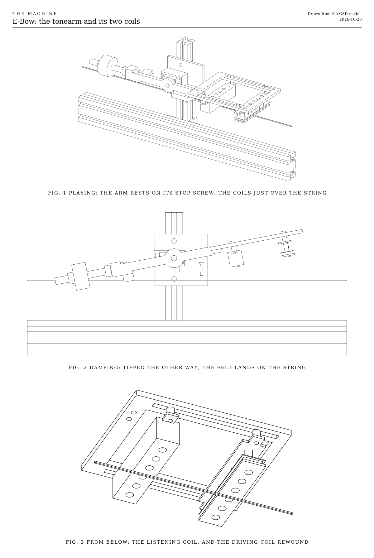
The tonearm and its two coils. The arm resting on its stop screw while it plays, the arm tipped back to damp the string, and the two coils seen from below. Drawn from the CAD model.
Fig. 1The tonearm and its two coils. The arm resting on its stop screw while it plays, the arm tipped back to damp the string, and the two coils seen from below. Drawn from the CAD model.

How it works

  • It keeps a string ringing without touching it. The E-Bow makes no sound of its own. It hangs over the steel string of another element, and that element’s pickup carries the note to the console.
  • Two coils hang just over the string. The nearer one is an ordinary guitar pickup, and it hears the string’s faintest trembling. A small amplifier, the kind sold to drive a little speaker, boosts what it hears. The farther coil is a pickup rewound with heavier wire. The amplified signal through it pulls the string toward it in time with the string’s own swing, so each swing comes back a little bigger.
  • The note swells, then holds. It grows until the amplifier runs out of room, then holds there, the amplifier putting back just what the string loses. That’s the e-bow sound: a note with no attack that swells in from nothing and lasts as long as it’s wanted.
  • Swapping the driving coil’s two wires plays an overtone. Each pull then comes at the wrong moment for the note itself, so the note dies away, and the string jumps up to an overtone that the reversed pull suits. A relay swaps the wires, so the firmware picks the note or the overtone each time. Which overtone depends on where the coils sit along the string.
  • A tonearm lowers it. Both coils hang from the end of an arm that pivots on a micro servo’s shaft, balanced by a counterweight. Tipped down, the arm rests on a stop screw with the coils 2 mm over the string, and the note swells. Tipped back, the coils lift clear and a felt on the arm’s other end lands on the string, so the note stops at once. In between, it parks with both clear, so the element it’s mounted on can play by itself.
  • It lands on the beat by starting early. From a still string a note takes a fraction of a second to a second or two to swell. The firmware lowers the arm early by the swell’s own time, so the note is full on its beat. It learns that time from every note, by reading how hard the amplifier is driving.
  • It’s an element of its own. It has its own ESP32 listening to Control on its own number, its own battery, and the stop button and relay every element has. It can play alone over a host that’s resting, or alongside the host’s own notes.

On its hosts

  • The Tension Glide String has room between its pickup and its wheel. Mount the E-Bow with its head reaching toward the saddle and the driving coil about 130 mm from it, just short of the wheel’s motor, which is where the model has it. The upright then stands where the Tension Glide keeps its electronics box, so slide the box along its slot toward the tuner first. The Tension Glide’s Bow Wheel lifts its wheel clear by itself while the E-Bow plays. With the E-Bow holding the note, every glide comes out pure and endless.
  • Lapless Steel is a tight fit. At the top of its range the sounding string runs only about 115 mm from the slide to the bridge, and that stretch already holds the pick and the pickup. The coils have to sit either side of the pickup, between the pick and the bridge, reaching toward the bridge. There the pickup hears some of the drive as a whine, and the low notes, with the slide far away, swell slowly. Its variation, riding the slide, is the better fit.

Notes

  • This is a first design, drawn but not yet built. The 3D model and the files show the version we started with, on a stand-in host. Bought parts vary, so check your pickups and servo against the numbers in the CAD script before printing.
  • The swell times and the gain are worked out from how e-bows and guitar sustainers behave, not yet measured on this build.
  • Costs in the ingredients are rough estimates for budgeting, not checked prices.
  • The firmware in the downloads is a first version. It compiles, and its timing and learning are tested against a simulated string, but it hasn’t yet run on a built element. It listens for Control, the one broadcast signal every element hears.

References

  • The EBow, made by Heet Sound, is the hand-held original. Its harmonic mode reverses its drive to damp the note and push an overtone, as the relay does here.
  • DIY Fever’s guitar sustainer rewinds a single-coil bobbin to 8 Ω with 0.2 mm wire and drives it from an LM386, as the driving coil here does. It also swaps the coil’s two wires for a harmonic mode.

Parts

Ingredients

KindPartQtySourceEachFile
PrintedServo saddle, holds the servo on the upright and the stop screw under the arm1··STL
PrintedArm, the tonearm from the servo's horn to the head, the felt and the counterweight1··STL
PrintedHead, the frame both coils hang under1··STL
BoughtV-slot extrusion, 20 x 20 mm, 165 mm long, the upright1·$4.00
BoughtCorner brackets for 20 mm V-slot, cast, with their M5 screws and T-nuts4·$1.00
BoughtM5 x 10 screws and T-nuts for 20 mm V-slotTwo for the servo saddle, and the rest for the box, the battery adapter and the stop button.8·$0.30
BoughtMicro servo, MG90S, with its horns and screwsMetal gears. The single-arm horn screws to the arm.1·$4.00
BoughtM3 x 16 screw with two nuts, the stop screw1·$0.20
BoughtSingle-coil guitar pickup, Strat size, the listening coilYour choice: see The bowAny Strat-size single coil. It hangs across the string, one pole right over it.1·$12.00
BoughtA second single-coil pickup, the cheapest you can find, to rewind as the driving coilYour choice: see The driving coilOnly its bobbin and poles are kept. Its fine wire comes off.1·$7.00
BoughtEnameled copper wire, 0.2 mm (32 AWG), a small spoolYour choice: see The driving coilAbout 15 m makes the 8 Ω coil.1·$6.00
BoughtPickup screws, M3 x 30, with springsThe kind that hold a pickup under a pickguard. Pickups often come with them.4·$0.30
BoughtLM386 amplifier module, gain 200, with its volume knobThe small board sold for driving a speaker from 5 to 12 V. Its knob becomes the gain.1·$2.00
BoughtRelay module, 2 channels, 5 V, high-level triggerSwaps the driving coil's two wires, for the overtone mode.1·$3.00
BoughtShielded cable, one core, about 1 mThe listening coil's lead to the amplifier.1·$2.00
BoughtWool felt, about 8 mm thick, a 16 x 12 mm pieceYour choice: see The damper1·$3.00
BoughtM8 threaded rod, 100 mm, with four M8 nuts and three fender washers, the counterweight1·$3.00
BoughtESP32-S3 development board1·$8.00
Bought5 V buck converter, 3 A1·$3.00
BoughtAdjustable buck converters, 3 A, one set to 6 V for the servo and one to 9 V for the amplifier2·$3.00
BoughtElectrolytic capacitors, 470 µF, 25 V, one on each adjustable converter's output2·$0.50
BoughtRelay module, 5 V, high-level trigger, contacts rated 10 AThe switch the servo's and the amplifier's power go through.1·$2.00
BoughtResistors, 10 kΩHold both relays off while the ESP32 starts.2·$0.10
BoughtFor the level reading, a 1N4148 diode, a 1 µF ceramic capacitor, a 100 kΩ resistor and two 47 kΩ resistors, on a scrap of perfboardLets the ESP32 hear how hard the amplifier is driving, so it can learn how long each swell takes.1·$1.00
BoughtBattery adapter for the shared power-tool platform1·$15.00
BoughtThe listener parts every element carries, as on the Control pageA blade fuse holder and 2 A fuse, a latching stop button with a spare contact, the status light, the number switches and their resistors. The stop switch under Choices has a plain two-pole switch in place of the stop button.1Link$12.00
BoughtMomentary push button, normally open, for the test buttonA short press plays each note once, and a long press relearns what the element can by itself. Any small panel button that closes while it's pressed will do.1·$1.00
BoughtSmall project box, about 70 x 60 x 40 mm, for the electronicsYour choice: see The electronics1·$6.00
SalvagedThin plastic, about 0.5 mm, a scrapFrom a blister pack or a lid. It becomes a new flatwork 3 mm from the poles' end, so the winding stays close to the string.1··
Total$109.00

Tools

  • 3D printer, PETG or PLA
  • Hex keys, 2, 2.5 and 3 mm
  • Small screwdriver
  • Soldering iron
  • Multimeter, to set the converters and measure the driving coil
  • A hand drill or a slow motor to turn the bobbin while winding, or patience
  • Fine sandpaper or a scalpel, to bare the wire's ends
  • Clear glue or varnish, to set the winding
  • An amp, or a cable to the console, to listen through the host's pickup

Choices

Decisions that are yours to make. Where we started is the version in the 3D model and the ingredients: a starting point, not the right answer.

The bow

What keeps the string ringing?

Two coils and a small amplifierWhere we started

SoundA pure, endless note that swells in from nothing, with a reedier edge as the gain goes up

About $40 in parts, with the copper on show. The ESP32 switches between the note and an overtone with a relay. Setting the gain between swelling and howling takes patience.

A bought EBow Plus, hung in place of the coils

SoundThe EBow's own smooth, singing tone, the one most people know from records

About $100, and the surest to work. Strap it under the head's frame, with its battery swapped for the 9 V converter. Its coils stay hidden in its case, and its standard or harmonic switch is set by hand.

A sustainer, with the host's own pickup listening

SoundMuch the same as the coils, though the host's output carries a little of the drive

Only the driving coil and the amplifier, so the fewest parts. It can only play over a host that has a magnetic pickup, wired to both the console and the amplifier.

Whichever bow, it makes no sound of its own. The string does, and the pickup of the element it's mounted on carries it to the console.

The driving coil

What pulls on the string?

A cheap single-coil pickup, rewoundWhere we started

SoundEnough to hold a wound string from a quarter of the way along

About 120 turns of 0.2 mm wire in a 3 mm band at the poles' end, to 8 Ω. Its six poles spread the pull over where six strings would be, so most of it goes to waste.

One pole, wound by hand

SoundStronger on a single string, so notes swell faster

The same wire to 8 Ω on one steel screw over a small magnet, about 15 mm across. More winding by hand, and the pole has to sit right over the string.

Whichever you wind, measure it before connecting it. Much under 4 Ω overloads the amplifier.

Where it sits

How far along the string is the head?

About a quarter of the way from one endWhere we started

SoundFull and round, and the overtone mode jumps clearly to an overtone

The string moves enough here for a quick swell, and both modes work.

Near the middle

SoundThe purest, most hollow note

The strongest pull on the note itself. The overtone mode is weaker here, and less sure which overtone it lands on.

Close to one end

SoundBright and reedy, rich in overtones, and its overtone mode jumps higher

The string barely moves near its ends, so notes swell slowly and want more gain.

Which overtone the overtone mode lands on depends on where the two coils sit. Slide the unit along its host, or slide the coils along the head, and listen.

The damper

What stops a note?

Wool feltWhere we started

SoundA clean, quick stop

A strip of piano damper felt or thick craft felt, glued under the arm's foot.

Leather

SoundA soft thud as it lands, and a slightly slower stop

Wears longer than felt.

None

SoundNotes ring away for several seconds after the coils lift, like a let-ring on a guitar

Leave the felt off. Stopping then does the same as letting go.

The stop switch

What cuts the servo's and the amplifier's power at the element?

Latching emergency-stop button, with a spare contactWhere we started

The red mushroom head anyone nearby knows to hit. It stays down until it's twisted to release, so the element can't start again by accident. Its main contact cuts the power and its spare contact tells the ESP32. About $8.

Two-pole power switch, a rocker or a toggle

Smaller, plainer and cheaper, about $2. One pole cuts the power and the other tells the ESP32, so it does the same job. It doesn't read as a stop to someone who doesn't know the Machine, and it switches back on as easily as off. Rate its contacts above what the element draws, as the button's are.

Keep the second pole either way. It tells the ESP32 the power was cut, so it parks the arm, with the relay back on the plain note, when the power comes back, as after a stop from the Bridge. Either way the relay stays, since it's how a stop from the Bridge reaches the element when no one is at it. A two-pole switch wires as the button does: one pole in place of the main contact, from 11 to 12, and the other in place of the spare contact, from 13 to 14.

Print

Material
PETG
Layers
0.2 mm
Walls
4
Infill
40%

There are three printed parts, and none needs supports. PETG holds its shape in a warm room; PLA is fine for a first try.

The printed parts

  • Servo saddle, holds the servo on the upright and the stop screw under the arm

    Which way up
    On its back, the flat side that meets the upright
    Supports
    None
    Time
    About 1.5 hours

    The servo's case drops into the frame, and its two tabs screw to the frame's face with the servo's own screws. The M3 nut for the stop screw presses into the pocket under the beam.

    STL ↓
  • Arm, the tonearm from the servo's horn to the head, the felt and the counterweight

    Which way up
    On its front face
    Supports
    None
    Time
    About 1.25 hours

    The horn screws to the back of the hub with its own two small screws. The hole through the hub lets a screwdriver reach the horn's middle screw.

    STL ↓
  • Head, the frame both coils hang under

    Which way up
    Flat
    Supports
    None
    Time
    About 1.25 hours
    STL ↓

Assembly

  1. 1

    Stand the upright behind the host, its front face against the host's back face, where the head will reach the stretch of string you want. Fix it with four corner brackets, two each side, into the host's upper and lower back slots.

    TrickySome elements keep their electronics or battery on their back face. Find a clear stretch first, at least 60 mm wide.

    CheckIt stands square to the host and doesn't rock when you push its top.

  2. 2

    Drop the servo into the saddle's frame, its shaft pointing out the front and its cable toward the notch, and screw its two tabs down with its own screws.

  3. 3

    Bolt the saddle to the upright's front face with two M5 screws into T-nuts, so the servo's shaft sits about 26 mm above the string.

    CheckLoosened, the saddle slides up and down the upright; tightened, it doesn't move.

  4. 4

    Unwind the second pickup's fine wire, keeping its bobbin and poles. Glue a strip of the thin plastic across the bobbin 3 mm from the poles' end, to make a narrow space for the new winding.

  5. 5

    Wind about 120 turns of the 0.2 mm wire into that space, dabbing clear glue every 20 turns, until it measures 8 Ω across its two ends. Mark the end you started from; the Wiring tab calls it the start.

    TrickyBare a millimeter of the wire partway through to measure as you go, then wind over it. Keep the turns tight and glued, or the coil buzzes when it drives.

    CheckAbout 8 Ω on the multimeter, and nothing at all between the wire and the poles.

  6. 6

    Hang the two coils under the head, poles down and long side across, each on two pickup screws with springs through the side slots. Put the listening coil nearer the arm and the driving coil at the far end, about 60 mm apart.

    CheckThey hang level, at the same height, and slide along the slots.

  7. 7

    Screw the horn to the back of the arm with its two small screws, and bolt the head on top of the arm's pad with two M3 screws.

  8. 8

    Glue your felt under the arm's foot. Fit the counterweight's rod through the boss with a nut each side, and thread the washers and two more nuts onto it.

  9. 9

    Mount the electronics box, the battery adapter and the stop button on the upright, and wire them as the Wiring tab shows.

    TrickyKeep the listening coil's cable apart from the driving coil's wires and the servo's. If the coils hear each other through their wires, it howls.

  10. 10

    Set the three converters to 5, 6 and 9 V with a multimeter before anything is connected to them.

  11. 11

    Turn the amplifier's knob all the way down. Load the firmware from the downloads and open its console. Type "servo 1500" to hold the servo in the middle of its turn, then push the arm's horn onto the shaft with the arm level and the coils over the string, and fit the horn's middle screw through the hub.

  12. 12

    Slide the counterweight's washers along the rod until the arm, let go, only just tips forward onto its stop screw by itself.

    TrickyToo heavy at the front and the servo strains to hold it parked; too light and it won't stay on its stop while it plays.

    CheckLift the head a little and let go. It sinks slowly onto the stop, not with a bang.

  13. 13

    Turn the stop screw until the coils' poles sit about 2 mm over the string, and lock it with its nut. Then set each coil's height with its two screws so both sit level.

    CheckA 2 mm strip of card slides between the poles and the string with a light touch.

  14. 14

    Find the arm's three positions with the console, as the firmware's README says, and save them. Playing rests the arm on its stop. Parked lifts the coils about 9 mm, with the felt still clear. Damping tips it far enough for the felt to press the string.

    CheckTyping "pose park" leaves the string free to ring when you pluck it; "pose damp" stops it dead.

  15. 15

    Type "pose play", then turn the amplifier's knob up slowly while you pluck the string lightly, until a plucked note holds instead of dying away.

    TrickyPast a point the coils start to hear each other and it howls with no string moving at all. Back the knob off until it stops, then a little more. The Tuning tab has more.

    CheckThe note holds steady, neither fading nor growing into a howl.

  16. 16

    Damp the string with a finger and let go, and listen to the note swell in on its own.

    CheckIt swells within a second or two.

  17. 17

    Type "mode overtone". The note should die away and the string jump up to a higher one. If instead the plain note holds, and it's "mode plain" that jumps, swap the driving coil's two wires at the relay.

  18. 18

    Play a few notes with "play 0" and "play 1" so it learns how long each kind of swell takes, then type "save".

Wiring

The fuse comes first, right after the battery. The ESP32 runs from the 5 V converter. The servo's 6 V converter and the amplifier's 9 V converter take their power through the stop button and then the relay, so either one cuts both. The listening coil feeds the amplifier, and the amplifier drives the driving coil through the second relay, which swaps its two wires for the overtone mode. The level reading lets the ESP32 hear how hard the amplifier is driving. The status light, the number switches and the battery reading are wired the same way on every element, so they're on the Control page, not here.

Wiring · E-Bow
PowerSignalGround, all joinedPins drawn faint are left empty.

Wire list

  1. Battery adapter, +

    Fuse, 2 A, in

    PowerRed, 16 AWG

    As short as the adapter allows. Nothing connects ahead of the fuse.

  2. Fuse, 2 A, out

    5 V converter, IN+

    PowerRed, 22 AWG

  3. Fuse, 2 A, out

    Stop button, 11

    PowerRed, 18 AWG

  4. Stop button, 12

    Relay module, power, COM

    PowerRed, 18 AWG

    The stop button's main contact opens when pressed, cutting the servo's and the amplifier's power itself, so a program that hangs can't ignore it.

  5. Relay module, power, NO

    6 V converter, servo, IN+

    PowerRed, 20 AWG

  6. Relay module, power, NO

    9 V converter, amplifier, IN+

    PowerRed, 20 AWG

  7. 5 V converter, OUT+

    ESP32-S3 board, 5V

    PowerRed, 22 AWG

    Only once the converter is set to 5 V.

  8. 5 V converter, OUT+

    Relay module, power, VCC

    PowerRed, 22 AWG

  9. 5 V converter, OUT+

    Relay module, 2 channels, VCC

    PowerRed, 22 AWG

  10. 6 V converter, servo, OUT+

    Servo, MG90S, red +

    PowerRed, 22 AWG

    Only once the converter is set to 6 V.

  11. Capacitor, 470 µF, +

    6 V converter, servo, OUT+

    PowerThe capacitor's own leg

    Solder its legs straight onto the converter's output terminals. It covers the jump in current as the servo starts. The stripe on its side marks the − leg.

  12. 9 V converter, amplifier, OUT+

    LM386 amplifier module, VCC

    PowerRed, 22 AWG

    Only once the converter is set to 9 V. Most LM386 boards take no more than 12 V.

  13. Capacitor, 470 µF, +

    9 V converter, amplifier, OUT+

    PowerThe capacitor's own leg

  14. Battery adapter, −

    5 V converter, IN−

    GroundBlack, 22 AWG

  15. Battery adapter, −

    6 V converter, servo, IN−

    GroundBlack, 20 AWG

  16. Battery adapter, −

    9 V converter, amplifier, IN−

    GroundBlack, 20 AWG

  17. 5 V converter, OUT−

    ESP32-S3 board, GND

    GroundBlack, 22 AWG

  18. 6 V converter, servo, OUT−

    Servo, MG90S, brown −

    GroundBlack, 22 AWG

  19. Capacitor, 470 µF, −

    6 V converter, servo, OUT−

    GroundThe capacitor's own leg

  20. 6 V converter, servo, OUT−

    ESP32-S3 board, GND

    GroundBlack, 22 AWG

    So the servo's signal and the ESP32 share a ground.

  21. 9 V converter, amplifier, OUT−

    LM386 amplifier module, GND

    GroundBlack, 22 AWG

  22. Capacitor, 470 µF, −

    9 V converter, amplifier, OUT−

    GroundThe capacitor's own leg

  23. LM386 amplifier module, GND

    ESP32-S3 board, GND

    GroundBlack, 22 AWG

    The level reading measures against it.

  24. Relay module, power, GND

    ESP32-S3 board, GND

    GroundBlack, 22 AWG

  25. Relay module, 2 channels, GND

    ESP32-S3 board, GND

    GroundBlack, 22 AWG

  26. Resistor, 10 kΩ, 2

    ESP32-S3 board, GND

    GroundThe resistor's own leg

  27. Resistor, 10 kΩ, 2

    ESP32-S3 board, GND

    GroundThe resistor's own leg

  28. Stop button, 14

    ESP32-S3 board, GND

    GroundBlack, 22 AWG

  29. Test button, 2

    ESP32-S3 board, GND

    GroundBlack, 22 AWG

  30. Capacitor, 1 µF, 2

    ESP32-S3 board, GND

    GroundThe capacitor's own leg

  31. Resistor, 100 kΩ, 2

    ESP32-S3 board, GND

    GroundThe resistor's own leg

  32. Resistor, 47 kΩ, 2

    ESP32-S3 board, GND

    GroundThe resistor's own leg

  33. ESP32-S3 board, GPIO 5

    Relay module, power, IN

    SignalAny color, 22 AWG

    High gives the servo and the amplifier their power.

  34. Resistor, 10 kΩ, 1

    Relay module, power, IN

    SignalThe resistor's own leg

    Holds the relay off while the ESP32 starts, when its pins float.

  35. ESP32-S3 board, GPIO 16

    Relay module, 2 channels, IN1

    SignalAny color, 22 AWG

  36. ESP32-S3 board, GPIO 16

    Relay module, 2 channels, IN2

    SignalAny color, 22 AWG

    Both channels switch together, so the pair works as one double switch.

  37. Resistor, 10 kΩ, 1

    Relay module, 2 channels, IN1

    SignalThe resistor's own leg

    Holds both channels off while the ESP32 starts, so the coil starts in the plain mode.

  38. ESP32-S3 board, GPIO 38

    Servo, MG90S, orange signal

    SignalAny color, 22 AWG

  39. Stop button, 13

    ESP32-S3 board, GPIO 4

    SignalAny color, 22 AWG

    The stop button's spare contact, so the ESP32 knows it's been pressed.

  40. Test button, 1

    ESP32-S3 board, GPIO 14

    SignalAny color, 22 AWG

    The test button. The ESP32's own pull-up holds the pin high until it's pressed, so nothing else goes on this pin.

  41. Listening coil, hot

    LM386 amplifier module, IN

    SignalShielded cable, its center core

    On most single coils the white or yellow lead is hot and the black one is ground. Check yours.

  42. Listening coil, ground

    LM386 amplifier module, GND

    SignalShielded cable, its braid

    The braid connects here, at the amplifier, and nowhere else.

  43. LM386 amplifier module, OUT+

    Relay module, 2 channels, NC1

    SignalTwisted pair, 22 AWG

  44. LM386 amplifier module, OUT+

    Relay module, 2 channels, NO2

    SignalTwisted pair, 22 AWG

  45. LM386 amplifier module, OUT−

    Relay module, 2 channels, NO1

    SignalTwisted pair, 22 AWG

    OUT− is the amplifier's ground.

  46. LM386 amplifier module, OUT−

    Relay module, 2 channels, NC2

    SignalTwisted pair, 22 AWG

  47. Relay module, 2 channels, COM1

    Driving coil, start

    SignalTwisted pair, 22 AWG, the coil's own leads

    With the relay off, the winding's start gets the amplifier's output and its finish goes to ground. With it on, they swap.

  48. Relay module, 2 channels, COM2

    Driving coil, finish

    SignalTwisted pair, 22 AWG, the coil's own leads

  49. LM386 amplifier module, OUT+

    Diode, 1N4148, anode

    SignalAny color, 22 AWG

    The level reading. Through the diode, the amplifier's output charges the capacitor to the size of its swing.

  50. Diode, 1N4148, cathode

    Capacitor, 1 µF, 1

    SignalThe diode's own leg

  51. Diode, 1N4148, cathode

    Resistor, 100 kΩ, 1

    SignalThe diode's own leg

    Lets the reading fall again within a twentieth of a second.

  52. Diode, 1N4148, cathode

    Resistor, 47 kΩ, 1

    SignalThe diode's own leg

  53. Resistor, 47 kΩ, 2

    ESP32-S3 board, GPIO 2

    SignalAny color, 22 AWG

  54. Resistor, 47 kΩ, 1

    ESP32-S3 board, GPIO 2

    SignalThe resistor's own leg

    The two 47 kΩ resistors halve the reading, so even the amplifier's full swing stays under 2 V at the pin.

Get these right

Set the converters first
Adjustable converters come set to anything. Turn each one's screw with the battery in and a multimeter on its output until it reads 5.0, 6.0 or 9.0 V, and only then connect the board, the servo or the amplifier. More than about 6 V destroys the ESP32, and more than 12 V most LM386 boards.
Measure the driving coil
It should read about 8 Ω. Much under 4 Ω overloads the amplifier and makes it hot; much over 16 Ω and it pulls too weakly to sustain.
Never wire the amplifier's output straight to the ESP32
It swings to 9 V. The level reading's diode and resistors bring it down to a safe size.
Keep the coils' wires apart
The listening coil's lead is shielded, with its braid grounded only at the amplifier. Twist the driving coil's two wires together and run them on the other side of the arm. Wires that run together let the coils hear each other, and it howls.
Which way round
If the plain mode jumps to an overtone and the overtone mode holds the note, the driving coil is the wrong way round. Swap its two wires at COM1 and COM2.

Mounting

Everything fixes to the V-slot with T-nuts and screws, so the whole unit comes off one element with a hex key and goes onto another. It brings its own upright, so it needs nothing from its host but a stretch of the host's back face and a string over the top.

The upright
Behind the host, its front face against the host's back face. Four corner brackets join them, two each side, into the host's upper and lower back slots. Slide it along to put the head over the stretch of string you want.
The servo
Its printed saddle bolts to the upright's front face with two M5 screws into T-nuts. Loosen them and the whole saddle slides up or down to suit any string's height. Set the servo's shaft about 26 mm above the string.
The stop screw
Stands head-up in the saddle's beam under the arm, locked by a nut. It sets how close the coils come to the string.
The coils
Hang under the head's frame on pickup screws and springs, like pickups under a pickguard. The slots let them slide along the string and set how far apart they are.
The counterweight
On the M8 rod at the back of the arm. Slide its washers to balance the head.
The electronics
In a box on the upright's back face, above the battery.
The battery
The adapter sits low on the upright's back face, so the pack's weight hangs close to the host.
The stop button
On top of the upright, where a hand finds it.
Which way it reaches
The head reaches toward one end of the string, the counterweight toward the other. To reach the other way, mirror the saddle and the arm in your slicer before printing them.

The electronics

Hidden in a box, or on show?

Closed boxWhere we started

A small project box, bought or printed, on the upright's back face. Tidy, and it keeps the relays' clicks muffled, but it hides the electronics.

Open plate

The boards on standoffs on a flat plate on the upright's back face, with the wires dressed along the slot. The electronics become part of the look. It wants neat wiring, and nothing guards it from knocks.

DIN rail

A short length of 35 mm DIN rail on T-nuts, with each board in a snap-on holder. It looks like a control panel, and any board comes off with a flick. The holders add a few dollars.

Whichever you pick, keep the stop button on the outside, where anyone can reach it.

Its power

Its own battery, or its host's?

Its own batteryWhere we started

Truly standalone, so it moves between elements with nothing to rewire. One more pack to charge.

A lead from its host's battery adapter

No second pack. Run a lead from the host's adapter to the E-Bow's own fuse, so each keeps its own fuse, stop button and relay. It then goes wherever its host goes.

Tuning

Tuning

The test button
A short press plays each of its notes once, starting about a second after you let go: a swell, the stop, an overtone, then a note left to ring. Hold it for two seconds and it forgets how long its swells take, so the next of each kind is learned afresh. Do that after a new string or a turn of the gain, then press again to play one of each. It works only while the element is resting, with no Bridge in range or with the Bridge holding it silent. While it plays or is stopped, the button does nothing. A stop ends a test at once, and pressing again ends one early. The arm's three positions are still set at the console.
It howls, even with the string damped
The two coils are hearing each other directly. Turn the amplifier's knob down, slide the coils further apart, or raise the listening coil a little. Check that the listening coil's shielded cable runs apart from the driving coil's wires.
The note won't swell
Too little gain, or the coils are too far from the string. Turn the knob up a little, lower the stop screw, or lower the coils on their screws. If it still won't, it may be damping the note instead; try the other mode, and swap the driving coil's wires if that one holds.
It swells too slowly
More gain, coils closer to the string, or the head further from the string's ends all quicken it. A heavier string, or one pulled tighter, swells slower.
It jumps to an overtone in the plain mode
The plain mode's pull is backwards. Swap the driving coil's two wires at the relay.
A different overtone than you wanted
The overtone it lands on depends on where the coils sit along the string. Slide the coils closer together or further apart along the head, or slide the whole unit along its host.
A rough, reedy edge on every note
The amplifier is running out of room, which is what holds the note steady. Less gain gives a purer note that swells more slowly; more gives a buzzier one that swells fast.
It buzzes or rattles
A coil is touching the string at the top of its swing. Raise the stop screw a quarter turn.
The host's pickup whines or hums
The host's pickup hears the driving coil. Keep at least 100 mm between them, and turn the driving coil so its wires leave away from the pickup.
A note doesn't stop cleanly
The felt isn't reaching the string. Set the damping position a little further over, or glue on a thicker felt.
Notes land late
A swell longer than about a second can't start early enough, since notes are heard about a second ahead. More gain or coils closer to the string shorten it. Its console shows how many notes came late.

Variations

Riding Lapless Steel's slide
On Lapless Steel the coils can only sit near the bridge, where the low notes swell slowly. Bolting the head to the slide's plate instead, just past the slide rod, keeps the coils at the same place on the sounding length for every note. The plate has to carry the head, and the wires have to follow it.
One for each string
Over an element with several strings, a head for each, or one wide head with a coil pair for each string. One ESP32 can tip several arms and swap several relays.
Loudness from the firmware
A digital potentiometer, such as an X9C103 module, in place of the amplifier's knob lets the firmware set the gain for each note, so loudness changes how hard and fast it swells.
The ESP32 in the loop
The ESP32 can read the listening coil itself and drive the amplifier, filtering the string's sound to push only the overtone it's told. Much more firmware, but any overtone from anywhere along the string.
Wider apart, or closer together
The head's slots let the coils sit from about 50 to 90 mm apart. Further apart they hear each other less and take more gain; closer, they land on different overtones in the overtone mode.