Skip to content

The Machine · Recipes

Chime Ring

Design stage

Updated 2026-10-20

A ring of chime tubes hung level, each one a note, struck from above by the cannon. The cannon hangs on a turret in the middle and turns to the note; or the ring turns, past fixed cannons.

Loading the model

Drag to turn · scroll to zoom

Printed

3DWhere we started. One version of it: eight aluminum tubes, 23 to 32 cm long, hung level in a ring about 90 cm across inside a 110 cm cube of V-slot, with the Cannon hanging from the top on a pan-and-tilt turret, pointing 60 degrees down. The cannon's barrel is drawn as its outline. Press Play: it strikes the first tube, reels home and cocks, turns to the fourth tube and strikes it, then turns back. The shots are slowed ten times; everything else runs at its own speed. Printed parts are drawn in orange; everything else is bought.

Overview

Cost, roughly
About $370
Printing
About 7 hours, plus the Cannon's
Building
Two weekends, with the Cannon
Difficulty
Involved

Anatomy

1
Energy source
The cannon's spring, squeezed again each time it reels its teardrop home
2
Control
A turret turns the cannon to a tube, and the cannon fires on the beat
3
Sounding body
A ring of eight aluminum tubes, hung level on cords at their nodes
4
Reset
The cannon reels its teardrop home and re-cocks, and the turret turns to the next note
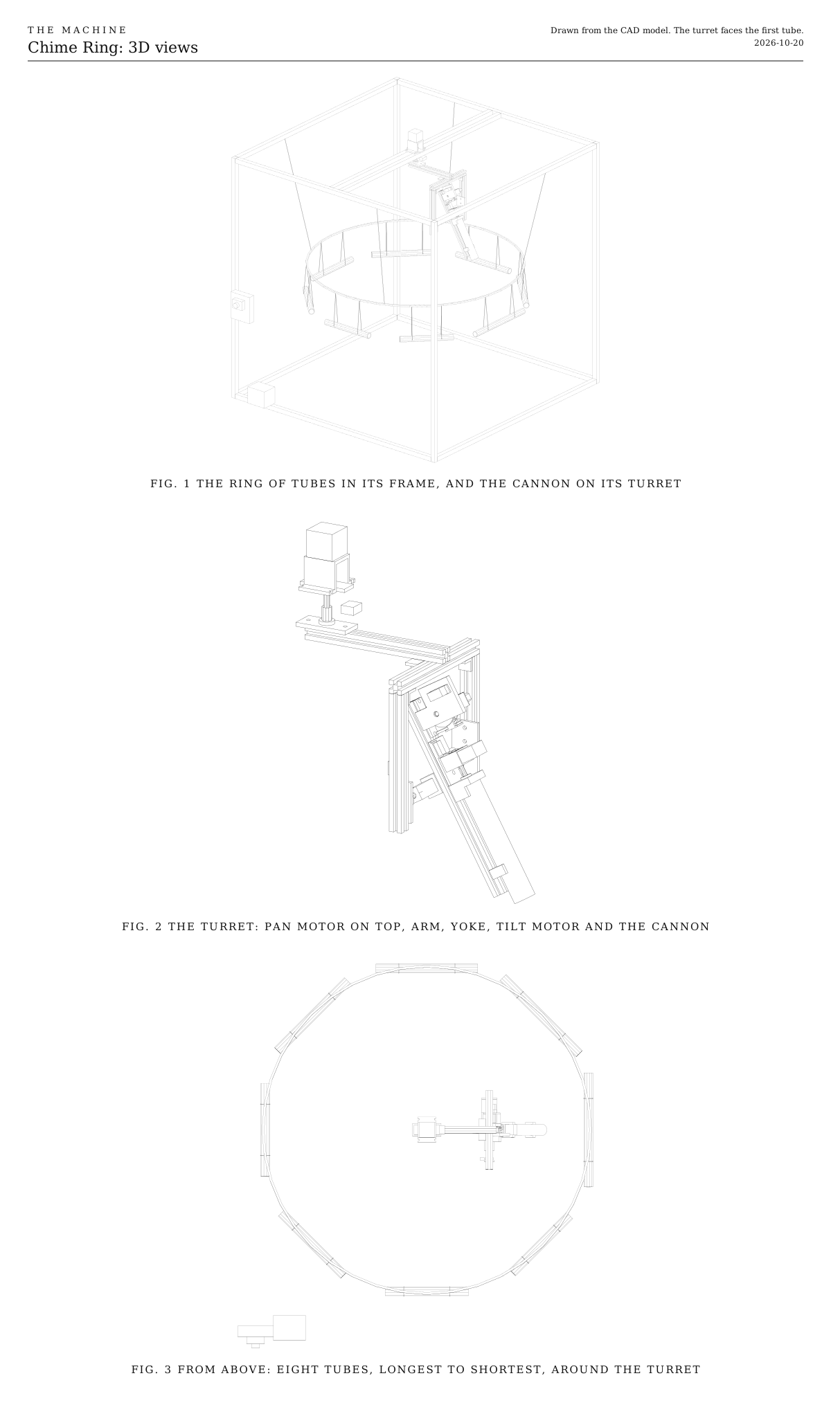
3D views. The ring of tubes in its frame with the cannon on its turret, the turret up close, and the ring from above. Drawn from the CAD model, facing the first tube.
Fig. 13D views. The ring of tubes in its frame with the cannon on its turret, the turret up close, and the ring from above. Drawn from the CAD model, facing the first tube.

How it works

  • Eight chime tubes hang level in a ring, each one a note. Each hangs on two cords at its nodes from a hoop overhead, and lies across the line from the middle of the ring, so its side faces the middle.
  • The Cannon hangs in the middle on a turret, upside down from the top of the frame. The turret turns it to face a tube, and it fires down and out at about 60 degrees, striking the tube’s middle square on. Its teardrop bounces back up its own path, swings under the cannon on its tether, and is reeled home, re-cocking the cannon as it comes.
  • It fires from above for a reason. A tethered teardrop only comes home cleanly when it’s struck down from well above a target that faces it. Fired level, it whips round the muzzle as it’s reeled in. The Cannon’s page explains why. So the cannon hangs over the ring, and the tubes hang level.
  • Something has to turn to pick the note. Either the cannon turns to face a tube, or the ring turns to bring a tube to the cannons. That is the main choice in this recipe, What turns, on the Parts tab. We started with the cannon on a turret.
  • The turret is two NEMA 17 steppers turning their loads directly. The pan motor sits on top of the frame and turns a shaft that hangs the whole turret from a flange bearing, so the motor carries no weight. The tilt motor tips the cannon, which hangs nearly balanced on its tilt axis.
  • One ESP32 runs it all. It listens for the wireless signal, turns the turret, and fires, brakes and reels the cannon. It runs from the shared power-tool battery.

Laying out the ring

  • Put the tubes in scale order round the ring. Neighboring notes are then small turns, and leaps are big swings the audience can follow.
  • Leave room between the tubes’ ends, so a struck tube can swing out on its cords and back without touching its neighbors. In the model, the closest ends are 3 cm apart.
  • Hang every tube’s middle at the same height and distance from the turret. The tilt can trim small differences, but each tube still has to lie square across its shot.
  • Keep everything out of the space under the cannon and inside the ring. After each hit, the teardrop swings through it on its tether.

Aiming and striking

  • Each tube gets a stored aim: a pan angle and a small tilt trim. Calibrate it once per tube, by firing and nudging until the strike lands in the middle, square on.
  • Each tube also gets a stored delay from cue to strike, about a tenth of a second. The firmware fires that much early, so the note lands on the beat.
  • The turret turns while the cannon reloads, so the next note can be ready in five to six seconds. Melodies are slow and stately, one note at a time.
  • Hold the turret still while a teardrop is out. A turning cannon would drag its tether across the tubes.

Four cannons and a turning ring

  • Four cannons reload in parallel, which gives up to four times the note rate and up to four notes at once.
  • Each hangs from the middle of a top edge of the cube, pointing down and inward at the ring, so the audience sees each one fire and reload. The ring hangs from a hub at the top center and turns to bring a tube under each cannon’s shot.
  • Hold the ring still while any teardrop is out, and turn it slowly. Spun fast, the tubes swing out on their cords and lose their aim.

Notes

  • This is a first design, drawn but not yet built. Expect one round of fitting.
  • The model shows the starting option, the cannon on a turret. The other two options aren’t drawn yet.
  • The motion in the 3D model is simulated with the Cannon’s own physics, with guesses for the shot’s speed and how much the teardrop bounces. A test build will give the real figures.
  • Costs in the parts list are rough estimates for budgeting, not checked prices. They add up the version we started with, including the Cannon.
  • The firmware isn’t written yet. It will listen for Control, the one broadcast signal every element hears.

References

  • OpenTurret is an open-source pan-and-tilt turret on two NEMA 17 steppers with belts and TMC2209 drivers, partly 3D printed. Its build documentation isn’t published yet. It inspired the turret here, which turns its loads directly instead of through belts.
  • Slip rings are rotary electrical joints that pass power onto a spinning part. The spinning-hub option needs one to turn past a full turn, unless its controller and battery ride on the hub.

Parts

Ingredients

KindPartQtySourceEachFile
PrintedMotor bridge, carrying the pan motor on top of the frame1··STL
PrintedHub plate, under the pan shaft's flange coupler1··STL
PrintedTilt plate, across the bottom of the cannon's spine1··STL
PrintedTilt motor bracket1··STL
FabricatedThe Cannon, built from its recipe, without its electronicsOne ESP32, one power supply and one box run both the cannon and the turret, so they're listed here instead.1Link$67.00
BoughtAluminum tube, 25 mm across, 1.5 mm wall, about 2.2 m, cut to 320, 302, 285, 277, 261, 247, 233 and 226 mmYour choice: see The tubesThose lengths are a starting point for a major scale. Cut each a few millimeters long and tune by trimming.1·$20.00
BoughtBraided cord, about 2 mm, about 6 mTwo cords per tube, through a hole at each node.1·$6.00
BoughtSteel hoop, about 92 cm acrossA macramé or wreath ring. The tubes hang from it.1·$12.00
BoughtFour cords and four screw hooks, to hang the hoop from the frame1·$4.00
BoughtAluminum extrusion, 20 x 20 V-slot, for the frame and the turretFour posts of 1100 mm, eight bars of 1060 mm and two center bars of 1060 mm for the cube. For the turret, an arm of 225 mm, a crossbar of 220 mm and two uprights of 205 mm.1·$110.00
BoughtThree-way corner brackets for 20 mm V-slot8·$2.00
BoughtCorner brackets for 20 mm V-slot, with screws and T-nutsFour for the center bars, and eight for the turret's arm, crossbar and uprights.12·$1.00
BoughtNEMA 17 stepper motor, 40 mm bodyOne turns the turret, one tilts the cannon. Both turn their loads directly.2·$12.00
BoughtFlange bearing for an 8 mm shaft (KFL08)One carries the turret's weight on the center bars, so the pan motor carries none. The other carries the tilt axis's free end.2·$3.00
BoughtSteel shaft, 8 mm, about 130 mm, cut to 85 mm for the pan and 40 mm for the tilt1·$4.00
BoughtShaft couplers, 5 to 8 mm (pan), and 5 mm and 8 mm rigid flange couplers (tilt and hub)1·$9.00
BoughtShaft collar, 8 mmRests on the pan bearing and holds the turret up by its shaft.1·$1.00
BoughtMicro switches with roller levers, for homingGive the pan and the tilt a known starting point when the power comes on.2·$1.00
BoughtTMC2209 stepper driverQuiet enough that the steppers don't whine between notes.2·$6.00
BoughtElectrolytic capacitors, 100 µF, 35 VOne across each driver's motor supply.2·$1.00
BoughtESP32 development board1·$6.00
BoughtBattery adapter for the shared power-tool platform, and a 5 V buck converter1·$15.00
BoughtAdjustable buck converter, set to 12 V, 3 AFor the cannon's gearmotor and catch.1·$3.00
BoughtThe listener parts every element carries, as on the Control pageA blade fuse holder (here with a 3 A fuse), a latching stop button with a spare contact, the status light, the number switches and their resistors. The stop switch under Choices has a plain two-pole switch in place of the stop button.1Link$12.00
BoughtMomentary push button, normally open, for the test buttonA short press plays each note once, and a long press relearns what the element can by itself. Any small panel button that closes while it's pressed will do.1·$1.00
BoughtRelay module, 5 V, high-level trigger, contacts rated 10 A1·$2.00
BoughtThe cannon's switching parts, two MOSFETs (IRLB8721), two diodes (1N5819), two 100 Ω and three 10 kΩ resistors, a 100 µF 25 V capacitor1·$4.00
BoughtSmall project box, for the electronicsYour choice: see The electronics1·$5.00
BoughtTwelve-core cable for the cannon, and four-core cable for the tilt motor and the two switches, about 2 m each1·$8.00
BoughtM5 screws and T-nuts, M3 screws, assorted1·$6.00
Total$369.00

Tools

  • 3D printer, PETG
  • Hex keys, 2.5, 3 and 4 mm
  • Tube cutter or fine hacksaw, and a file to deburr
  • A drill with a 3 mm bit, and a center punch, for the tubes' cord holes
  • A tuner, or a tuning app on a phone
  • Soldering iron and heat-shrink, for the wiring
  • A multimeter, to set the converters
  • A square, to set the frame and the tubes

Choices

Decisions that are yours to make. Where we started is the version in the 3D model and the ingredients: a starting point, not the right answer.

What turns

Something has to turn to pick the note. Does the cannon turn to face a tube, or does the ring turn to bring a tube to the cannons?

The cannon, on a turretWhere we started

SoundOne note at a time, every five or six seconds. The audience watches the cannon swing to its note before each strike, and the swing is part of the piece.

The turret hangs upside down from the top of the frame, on two NEMA 17 steppers turning it directly, with no belts. The tilt trims each tube's aim in software and lets tubes hang at different heights. Its cables follow it within one turn, so from the last tube to the first it turns back the long way.

The cannon, on a spinning hub

SoundOne note at a time, at the same pace.

One stepper turns it, and the tilt is fixed at 60 degrees, so it's cheaper and simpler. Every tube has to hang at the same height and distance, set by hand on its cords. Spinning on past a full turn needs a slip ring, or a battery and a controller riding on the hub.

The ring, turning past four fixed cannons

SoundUp to four notes at once, and up to four times the note rate of one cannon. Each set of four tubes, 90 degrees apart, can be tuned as a chord, and turning the ring changes the chord.

Four Cannons to build, one at the middle of each top edge of the cube, pointing 60 degrees down and inward, and a motor at the top center to turn the hoop. It costs the most and takes the most work. Nothing that turns carries wires, so there's no slip ring. The ring has to hold still whenever a teardrop is out.

In all three, the cannon fires down from above at tubes hung level. That's how its teardrop comes home cleanly; the Cannon's page explains why.

The tubes

What are the chimes made of?

Aluminum tubeWhere we started

SoundBright and clear, with a long ring

Light and cheap, and easy to cut and tune. Being light, a struck tube swings a little on its cords. 25 mm across, 1.5 mm wall.

Brass or copper tube

SoundWarmer and darker, with a long, soft decay

Heavier, so the strike swings it less. It costs several times as much and tarnishes unless lacquered.

Steel electrical conduit

SoundLouder and clangier, with a shorter ring

The cheapest, from any hardware store. It rusts unless painted, and its seam can make two notes beat against each other.

The same note needs a different length in a different tube, so cut long and tune by trimming.

The notes

Which notes are in the ring?

A major scale of eightWhere we started

SoundAn octave from the longest tube to the shortest, so tunes can be played

Eight tubes, 23 to 32 cm, laid round the ring in order, so steps between neighboring notes are small turns and leaps are big ones.

A pentatonic five

SoundAny notes together sound good, so it can't play a wrong note

Five tubes with more room between them, and longer turns between notes.

All twelve

SoundEvery note in the octave

Twelve tubes need a ring about half again as wide, a longer arm on the turret and a bigger frame.

The stop switch

What cuts the power to everything that moves at the element?

Latching emergency-stop button, with a spare contactWhere we started

The red mushroom head anyone nearby knows to hit. It stays down until it's twisted to release, so the element can't start again by accident. Its main contact cuts the power and its spare contact tells the ESP32. About $8.

Two-pole power switch, a rocker or a toggle

Smaller, plainer and cheaper, about $2. One pole cuts the power and the other tells the ESP32, so it does the same job. It doesn't read as a stop to someone who doesn't know the Machine, and it switches back on as easily as off. Rate its contacts above what the element draws, as the button's are.

Keep the second pole either way. The ESP32 knows where the turret is only by counting the steps it sends, so the second pole is how it learns the power was cut, and finds the pan and tilt switches again before it moves. Without it, a turret turned by hand while it was off could aim the cannon at the wrong tube. Either way the relay stays, since it's how a stop from the Bridge reaches the element when no one is at it. A two-pole switch wires as the button does: one pole in place of the main contact, from 11 to 12, and the other in place of the spare contact, from 13 to 14.

Print

Material
PETG
Layers
0.2 mm
Walls
4, and 6 for the hub plate and the tilt plate
Infill
40%, and 60% for the hub plate and the tilt plate

Every part fits a 150 mm bed and prints without supports. The hub plate and the tilt plate carry the turret and the cannon, so print them strong.

The printed parts

  • Motor bridge, carrying the pan motor on top of the frame

    Which way up
    As it stands, feet down
    Supports
    None
    Time
    About 2 hours 15 minutes

    The top bridges 32 mm between the legs. Print it with your printer's bridging settings, or sand the underside if it sags.

    STL ↓
  • Hub plate, under the pan shaft's flange coupler

    Which way up
    Flat
    Supports
    None
    Time
    About 1 hour

    The whole turret hangs from it. Print it with six walls and 60% infill.

    STL ↓
  • Tilt plate, across the bottom of the cannon's spine

    Which way up
    Top face down
    Supports
    None
    Time
    About 2 hours 30 minutes

    The cannon hangs from it. Print it with six walls and 60% infill. The 8 mm stub shaft is glued into its hole.

    STL ↓
  • Tilt motor bracket

    Which way up
    On its side
    Supports
    None
    Time
    About 1 hour 15 minutes
    STL ↓

Assembly

  1. 1

    Build the Cannon from its recipe, all but its electronics.

    CheckFired and reeled by hand, it comes home and cocks.

  2. 2

    Build the cube. Four posts stand on three-way corner brackets with the bottom bars, and the top bars close it the same way.

    CheckMeasured corner to corner, the two diagonals of each face match within 2 mm, and the cube doesn't rock on a flat floor.

  3. 3

    Fix the two center bars across the top, 48 mm apart between their middles, with two corner brackets at each end.

  4. 4

    Bolt the flange bearing on top of the center bars, straddling the gap between them, with two M5 screws into T-nuts. Push the pan shaft down through it, put the collar on top of the bearing, and fit the rigid flange coupler to the shaft's bottom end.

    TrickyThe collar carries the whole turret, about 1.5 kg, through the bearing. Tighten its screw hard on a flat filed on the shaft, so it can't slip down.

  5. 5

    Screw the pan motor face down onto the motor bridge, push the coupler onto its shaft, stand the bridge over the bearing so the coupler meets the pan shaft, and bolt its feet to the center bars.

    CheckTurned by hand, the shaft turns the motor smoothly, and lifting the shaft doesn't move the motor.

  6. 6

    Screw the hub plate to the flange coupler, and bolt the arm under it. Hang the crossbar under the arm's outer end and the two uprights under the crossbar's ends, with corner brackets.

    CheckThe yoke hangs square, the uprights 180 mm apart on the inside.

  7. 7

    Screw the tilt plate across the bottom of the cannon's spine, 105 to 135 mm from its back end, with two M5 screws into T-nuts. Glue the stub shaft into its hole.

    TrickyThe cannon should nearly balance on the tilt axis, so the tilt motor has little to hold. Before gluing, rest the stub shaft and the coupler's boss on two fingers, and slide the plate along the spine until the cannon hangs pointing about 60 degrees down by itself.

  8. 8

    Bolt the second flange bearing to the inner face of the -Y upright, and the tilt motor on its bracket to the inner face of the +Y upright. Lift the cannon between them, slide the stub shaft into the bearing, and couple the motor's shaft to the tilt plate.

    CheckThe cannon tilts freely by hand with the motor unpowered, and stops wherever you leave it, or close to it.

  9. 9

    Fit the pan home switch under the center bars, where the arm's root presses it, and the tilt home switch on the -Y upright, where the tilt plate presses it at the top of its travel.

  10. 10

    Cut the tubes a few millimeters long, deburr their ends, and drill a 3 mm hole across each one at both nodes, 22.4% of its length in from each end.

    TrickyThe nodes are where the tube hardly moves as it rings. Hung anywhere else, the cords damp it and the note dies quickly. Measure each tube's own length, not the list.

  11. 11

    Tune each tube with a tuner, tapping it with a hard plastic mallet as it hangs from a finger at one node. Trim it shorter to raise its note, a millimeter at a time.

    TrickyOnce it's too short, the note can only go up. Cut long and creep toward the note.

  12. 12

    Hang the hoop from the frame's top bars on four cords, level, 25 cm below the tilt axis and centered under the turret. Hang each tube level on two cords through its holes, from the hoop, with its middle 45 cm out from the turret's axis and 40 cm below the tilt axis.

    CheckSeen from the cannon, each tube lies square across the line of its shot, and each tube's middle is the same height.

  13. 13

    Wire it, following the wire list under Wiring. Run the cannon's cable and the tilt motor's cable up the front left post, along the top, and down beside the pan shaft, with a loose loop at the top that lets the turret turn once each way.

    TrickySet both converters with a multimeter before connecting anything to them. More than about 6 V on the 5 V side destroys the ESP32.

    CheckWith the battery in and no code running, nothing moves and the ESP32's light is on. Press the stop button, release it, and nothing moves.

  14. 14

    Load the firmware. It homes the pan and the tilt slowly against their switches.

    CheckThe turret turns to face the first tube and the cannon tips to 60 degrees down.

  15. 15

    Aim at each tube in turn. Fire, watch where the teardrop lands, nudge the turret's pan and tilt from the bench console until it strikes the middle of the tube square on, and store that aim with the tube. Measure the time from cue to strike for each tube too.

    TrickyThe teardrop has to bounce straight back up its path. If it comes home swinging wide from one tube, that tube isn't square to the shot. Turn it on its cords rather than aiming off-center.

    CheckEvery tube rings from a strike at its middle, and each teardrop comes home tail first.

Wiring

One ESP32 runs the cannon and the turret. The fuse comes first, right after the battery. The ESP32 and the cannon's brake run from the 5 V converter. Everything that moves runs after the stop button and then the relay, so either one cuts it: the two stepper drivers straight from the battery's voltage, and the cannon's gearmotor and catch at 12 V from a second converter. The cannon is wired exactly as on its own page, with its signals on the same pins. The status light, the number switches and the battery reading are wired the same way on every element, so they're on the Control page, not here.

Wiring · Chime Ring
PowerSignalMotorGround, all joinedPins drawn faint are left empty.

Wire list

  1. Battery adapter, +

    Fuse, 3 A, in

    PowerRed, 16 AWG

    As short as the adapter allows. Nothing connects ahead of the fuse.

  2. Fuse, 3 A, out

    5 V converter, IN+

    PowerRed, 22 AWG

  3. Fuse, 3 A, out

    Stop button, 11

    PowerRed, 18 AWG

  4. Stop button, 12

    Relay module, COM

    PowerRed, 18 AWG

    The stop button's main contact opens when pressed, cutting the power to everything that moves, so a program that hangs can't ignore it.

  5. Relay module, NO

    12 V converter, IN+

    PowerRed, 18 AWG

  6. Relay module, NO

    TMC2209, pan, VM

    PowerRed, 18 AWG

  7. Relay module, NO

    TMC2209, tilt, VM

    PowerRed, 18 AWG

  8. Capacitor, 100 µF, +

    TMC2209, pan, VM

    PowerThe capacitor's own leg

    Solder its legs straight onto the driver's VM and GND pins. The stripe on its side marks the − leg.

  9. Capacitor, 100 µF, +

    TMC2209, tilt, VM

    PowerThe capacitor's own leg

  10. 12 V converter, OUT+

    Catch (lock solenoid), +

    PowerRed, in the cannon's cable

  11. 12 V converter, OUT+

    Gearmotor, +

    PowerRed, in the cannon's cable

  12. Capacitor, 100 µF, +

    12 V converter, OUT+

    PowerThe capacitor's own leg

  13. 5 V converter, OUT+

    ESP32 board, 5V

    PowerRed, 22 AWG

    Only once the converter is set to 5 V.

  14. 5 V converter, OUT+

    Relay module, VCC

    PowerRed, 22 AWG

  15. 5 V converter, OUT+

    Brake servo, 5V

    PowerRed, in the cannon's cable

    The stop button doesn't cut the cannon's brake. It holds the spool, which is what you want when everything stops.

  16. ESP32 board, 3V3

    Spool sensor, VCC

    PowerIn the cannon's cable

  17. ESP32 board, 3V3

    TMC2209, pan, VDD

    PowerRed, 22 AWG

    The drivers' logic runs at the ESP32's 3.3 V, so their signals match.

  18. ESP32 board, 3V3

    TMC2209, tilt, VDD

    PowerRed, 22 AWG

  19. Catch (lock solenoid), −

    MOSFET for the catch, D

    PowerIn the cannon's cable

    Seen from the front, the MOSFET's legs are G, D and S, left to right.

  20. Catch (lock solenoid), −

    Diode, 1N5819, A

    PowerThe diode's own leg

  21. Diode, 1N5819, K

    Catch (lock solenoid), +

    PowerThe diode's own leg

    Across the solenoid's two leads at the cannon, stripe toward +.

  22. Gearmotor, −

    MOSFET for the gearmotor, D

    PowerIn the cannon's cable

  23. Gearmotor, −

    Diode, 1N5819, A

    PowerThe diode's own leg

  24. Diode, 1N5819, K

    Gearmotor, +

    PowerThe diode's own leg

    Across the gearmotor's two tabs, stripe toward +.

  25. Battery adapter, −

    5 V converter, IN−

    GroundBlack, 22 AWG

  26. Battery adapter, −

    12 V converter, IN−

    GroundBlack, 18 AWG

  27. Battery adapter, −

    TMC2209, pan, GND

    GroundBlack, 18 AWG

    The motor's return. Use the driver's GND pin next to VM.

  28. Battery adapter, −

    TMC2209, tilt, GND

    GroundBlack, 18 AWG

  29. Capacitor, 100 µF, −

    TMC2209, pan, GND

    GroundThe capacitor's own leg

  30. Capacitor, 100 µF, −

    TMC2209, tilt, GND

    GroundThe capacitor's own leg

  31. 12 V converter, OUT−

    MOSFET for the catch, S

    GroundBlack, 22 AWG

  32. 12 V converter, OUT−

    MOSFET for the gearmotor, S

    GroundBlack, 22 AWG

  33. Capacitor, 100 µF, −

    12 V converter, OUT−

    GroundThe capacitor's own leg

  34. 5 V converter, OUT−

    ESP32 board, GND

    GroundBlack, 22 AWG

  35. ESP32 board, GND

    MOSFET for the gearmotor, S

    GroundBlack, 22 AWG

    The MOSFETs switch on the ESP32's signals, so they have to share its ground.

  36. ESP32 board, GND

    TMC2209, pan, GND

    GroundBlack, 22 AWG

    The driver's other GND pin, next to VDD.

  37. ESP32 board, GND

    TMC2209, tilt, GND

    GroundBlack, 22 AWG

  38. Relay module, GND

    ESP32 board, GND

    GroundBlack, 22 AWG

  39. Resistor, 10 kΩ, 2

    ESP32 board, GND

    GroundThe resistor's own leg

  40. Resistor, 10 kΩ, 2

    MOSFET for the catch, S

    GroundThe resistor's own leg

  41. Resistor, 10 kΩ, 2

    MOSFET for the gearmotor, S

    GroundThe resistor's own leg

  42. Brake servo, GND

    ESP32 board, GND

    GroundBlack, in the cannon's cable

    The servo, the sensor and the cocked switch share one ground core in the cannon's cable.

  43. Spool sensor, GND

    ESP32 board, GND

    GroundIn the cannon's cable

  44. Cocked switch, COM

    ESP32 board, GND

    GroundIn the cannon's cable

  45. Pan home switch, COM

    ESP32 board, GND

    GroundBlack, 22 AWG

  46. Tilt home switch, COM

    ESP32 board, GND

    GroundIn the cannon's cable, on the shared ground core

  47. Stop button, 14

    ESP32 board, GND

    GroundBlack, 22 AWG

  48. Test button, 2

    ESP32 board, GND

    GroundBlack, 22 AWG

  49. ESP32 board, GPIO 33

    Relay module, IN

    SignalAny color, 22 AWG

  50. Resistor, 10 kΩ, 1

    Relay module, IN

    SignalThe resistor's own leg

    Holds the relay off while the ESP32 starts, when its pins float.

  51. ESP32 board, GPIO 25

    Resistor, 100 Ω, 1

    SignalAny color, 22 AWG

  52. Resistor, 100 Ω, 2

    MOSFET for the catch, G

    SignalThe resistor's own leg

  53. Resistor, 10 kΩ, 1

    MOSFET for the catch, G

    SignalThe resistor's own leg

    Holds the catch off while the ESP32 starts. Without it, a floating pin could fire the cannon as it powers up.

  54. ESP32 board, GPIO 26

    Resistor, 100 Ω, 1

    SignalAny color, 22 AWG

  55. Resistor, 100 Ω, 2

    MOSFET for the gearmotor, G

    SignalThe resistor's own leg

  56. Resistor, 10 kΩ, 1

    MOSFET for the gearmotor, G

    SignalThe resistor's own leg

  57. ESP32 board, GPIO 27

    Brake servo, SIG

    SignalIn the cannon's cable

  58. ESP32 board, GPIO 16

    TMC2209, pan, STEP

    SignalAny color, 22 AWG

  59. ESP32 board, GPIO 17

    TMC2209, pan, DIR

    SignalAny color, 22 AWG

  60. ESP32 board, GPIO 18

    TMC2209, tilt, STEP

    SignalAny color, 22 AWG

  61. ESP32 board, GPIO 23

    TMC2209, tilt, DIR

    SignalAny color, 22 AWG

  62. ESP32 board, GPIO 4

    TMC2209, pan, EN

    SignalAny color, 22 AWG

    Low turns the motors on. One pin enables both drivers.

  63. ESP32 board, GPIO 4

    TMC2209, tilt, EN

    SignalAny color, 22 AWG

  64. Cocked switch, NO

    ESP32 board, GPIO 32

    SignalIn the cannon's cable

    Closed while the cannon is cocked. A broken wire reads as not cocked, so the cannon holds in a fault rather than thinking it's ready.

  65. Spool sensor, DO

    ESP32 board, GPIO 19

    SignalIn the cannon's cable

  66. Pan home switch, NC

    ESP32 board, GPIO 21

    SignalAny color, 22 AWG

    The switch's normally closed contact, which opens when pressed. A broken wire then reads as pressed, so the turret stops rather than turning on.

  67. Tilt home switch, NC

    ESP32 board, GPIO 22

    SignalIn the cannon's cable, on a spare core

  68. Stop button, 13

    ESP32 board, GPIO 13

    SignalAny color, 22 AWG

    The stop button's spare contact, so the ESP32 knows it's been pressed.

  69. Test button, 1

    ESP32 board, GPIO 15

    SignalAny color, 22 AWG

    The test button. The ESP32's own pull-up holds the pin high until it's pressed. The board reads GPIO 15 as it starts, but only to choose whether to print, so holding the button then does no harm.

  70. TMC2209, pan, 1A

    Pan stepper, A1

    MotorThe motor's own cable

    1A and 1B go to one coil, 2A and 2B to the other.

  71. TMC2209, pan, 1B

    Pan stepper, A2

    MotorThe motor's own cable

  72. TMC2209, pan, 2A

    Pan stepper, B1

    MotorThe motor's own cable

  73. TMC2209, pan, 2B

    Pan stepper, B2

    MotorThe motor's own cable

  74. TMC2209, tilt, 1A

    Tilt stepper, A1

    MotorIn the four-core cable to the turret

  75. TMC2209, tilt, 1B

    Tilt stepper, A2

    MotorIn the four-core cable to the turret

  76. TMC2209, tilt, 2A

    Tilt stepper, B1

    MotorIn the four-core cable to the turret

  77. TMC2209, tilt, 2B

    Tilt stepper, B2

    MotorIn the four-core cable to the turret

Get these right

Set both converters first
Most converters come set higher than you want. With the battery in and a multimeter on each output, turn the 5 V one to 5.0 V and the 12 V one to 12.0 V, and only then connect anything to them. More than about 6 V destroys the ESP32.
The cables to the turret
Everything on the turret reaches it through two cables: the cannon's twelve-core cable, as on the Cannon's page, and a four-core cable for the tilt motor. The tilt home switch shares the cannon's spare cores: one for its signal, and the shared ground. Leave a loose loop above the pan shaft, enough for the turret to turn once each way.
Never unplug a stepper with power on
Disconnecting a running stepper can destroy its driver. Press the stop button first.
Finding a stepper's coils
Motor wire colors vary by maker. Touch two wires together and turn the shaft by hand; if it suddenly turns stiffly, those two are one coil. If a motor runs backwards, swap the two wires of one coil.
The pins
Any free ESP32 pins will do, except 0, 2, 5 and 12, which the board reads as it starts, and 34 to 39, which have no pull-up for the switches. The board reads 15 as it starts too, but only to choose whether to print, so 15 carries the test button on every element. On a board with extra memory (a WROVER), 16 and 17 are taken too, so move the pan driver's pins. If you use others, the firmware needs to know.

Mounting

Everything fixes to a cube of 20 x 20 V-slot with T-nuts and screws, so any part can slide to a new place or come off with a hex key. The turret hangs from the top, the tubes hang from a hoop below it, and the space under the cannon stays clear for the teardrop's swing after each hit.

The cube
Four posts of 1100 mm and eight bars between them, joined at each corner by a three-way corner bracket.
The center bars
Two bars across the top, front to back, 48 mm apart between their middles, each fixed to the front and back top bars with a corner bracket either side.
The pan bearing and motor
The flange bearing bolts on top of the center bars, across the gap between them. The motor bridge stands over it on the bars, with the pan motor face down on top, so the motor sits on top of the frame.
The turret
The hub plate screws to the flange coupler on the pan shaft's bottom end. The arm bolts under the hub plate, the crossbar hangs under the arm's outer end, and the two uprights hang from the crossbar's ends, all with corner brackets.
The cannon
The tilt plate screws across the bottom slot of the cannon's spine, and the cannon hangs between the two uprights on the tilt axis. The stub shaft turns in a flange bearing on one upright, and the tilt motor on its bracket on the other upright turns the plate through a flange coupler.
The hoop
Four cords from screw hooks in the top bars hang it level, centered under the turret, about 25 cm below the tilt axis.
The tubes
Each hangs level on two cords at its nodes, from the hoop, its middle 45 cm out from the turret's axis and 40 cm below the tilt axis, lying square across the line of its shot.
The home switches
The pan switch on a V-slot switch mount under the center bars, pressed by the arm's root at the turret's starting point. The tilt switch on the inner face of the -Y upright, above the flange bearing.
The electronics
In a box on the front left post, about 40 cm up, on two T-nuts. The cables run up the post's slot, along the top bar and down beside the pan shaft.
The battery and the stop button
The battery adapter sits on the bottom front bar, beside the post. The stop button is on the outside of the electronics box, where a technician's hand finds it.

The electronics

Hidden in a box, or on show?

Closed boxWhere we started

A small project box on a post. Tidy and safe from a stray teardrop, but it hides the electronics.

Open plate

The boards on standoffs on a flat plate on the post, the wires dressed along the slots. The electronics become part of the look, and they want neat wiring.

DIN rail

A short length of 35 mm DIN rail on T-nuts, each board in a snap-on holder. It looks like a control panel, and any board comes off with a flick.

Whichever you pick, keep the stop button on the outside, where anyone can reach it.

Tuning

Tuning

The test button
A short press plays each tube once, round the ring in scale order, about six seconds apart. Hold it for two seconds and it homes the pan and the tilt against their switches, and the cannon rewinds slowly and cocks. It works only while the element is resting, with no Bridge in range or with the Bridge holding it silent. While it plays or is stopped, the button does nothing. A stop ends a test at once, and pressing again ends one early. Each tube's aim and delay are still set at the console.
A tube rings sharp
It's too short for its note. Swap it with the next shorter tube's note, or cut a new one a little longer.
A tube rings flat
Trim it a millimeter at a time from one end, and redrill that end's node hole so it stays 22.4% in.
A tube buzzes, or its note dies quickly
Its cords aren't at its nodes, it's touching a neighbor or the hoop, or its cords are pinching it. Hang it freely from the cords alone.
Two neighbors clash when one is struck
The struck tube swings out on its cords and comes back. Shorten the cords a little, or move the tubes further apart round the ring.
A strike lands off the middle
Trim that tube's stored aim, not the tube. A strike near a node sounds dull.
The teardrop comes home swinging wide from one tube
That tube isn't square to the shot, so the teardrop leaves it sideways. Turn the tube on its cords until it lies straight across the shot.
The turret overshoots, and the cannon wobbles after a turn
The turret is turning too fast for its weight. Slow the turns, and give it a moment to settle before it fires.
A whine as the turret turns
The drivers aren't in their quiet mode. The TMC2209 has a near-silent mode for slow moves.
A note comes late
The turret has to finish turning and the cannon has to finish cocking before it can fire again, five to six seconds between notes. Write melodies that leave it that long, or use the four-cannon version.

Variations

Four cannons and a turning ring
The third option above. The hoop hangs from a motorized hub at the top center and turns, and four Cannons hang at the middles of the top edges, aimed down and inward. Hold the ring still whenever a teardrop is out, because a turning tube would catch an extended tether.
Two cannons on one turret
A second Cannon on the other end of the arm, facing the opposite way, plays the tube across the ring. It doubles the note rate for the cost of one more cannon, and the turret has to be balanced for it.
Mixed tubes
Tubes of different metals, or a few wooden bars, in one ring. Each has its own voice, and the cannon doesn't mind what it strikes as long as it lies square across the shot.
Hung from the ceiling
Without the cube, the turret and the hoop can hang from a ceiling or a beam, with the stop button and the electronics on a nearby wall.
More notes
A longer arm and a bigger frame make room for more and longer tubes. The cannon's shot stays the same, so the tubes stay 45 cm out from the turret's axis plus the arm's extra length.