Skip to content

The Machine · Recipes

Chain Drop

Design stage

Updated 2026-10-19

A chain wound in coils on a rod. A servo swings the rod from level to straight down, and the coils slide off the end and crash onto a drum. A second servo spins the rod and winds the chain on again.

Loading the model

Drag to turn · scroll to zoom

Printed

3DThree on one bar, sharing one control set. Three units hang over a snare, a sheet of steel and a cymbal, and take turns. Each is where we started: light steel chain on an 8 mm steel rod, and two MG996R servos in a pan-and-tilt bracket kit, the rod clamped to the winding servo by an aluminum coupler. The ingredients are for one unit; Several on one bar, under Tuning, covers sharing the control set. The flares are the only printed parts, drawn in orange. Press Play to see them drop and rewind.

Overview

Cost, roughly
About $110
Printing
About an hour, one part
Building
A few hours
Difficulty
Easy

Anatomy

1
Energy source
Chain coiled on a raised rod
2
Control
A servo swings the rod down; the coils slide off its end
3
Sounding body
Snare, cymbal, sheet metal
4
Reset
The rod swings back to level; a second servo winds the chain back on
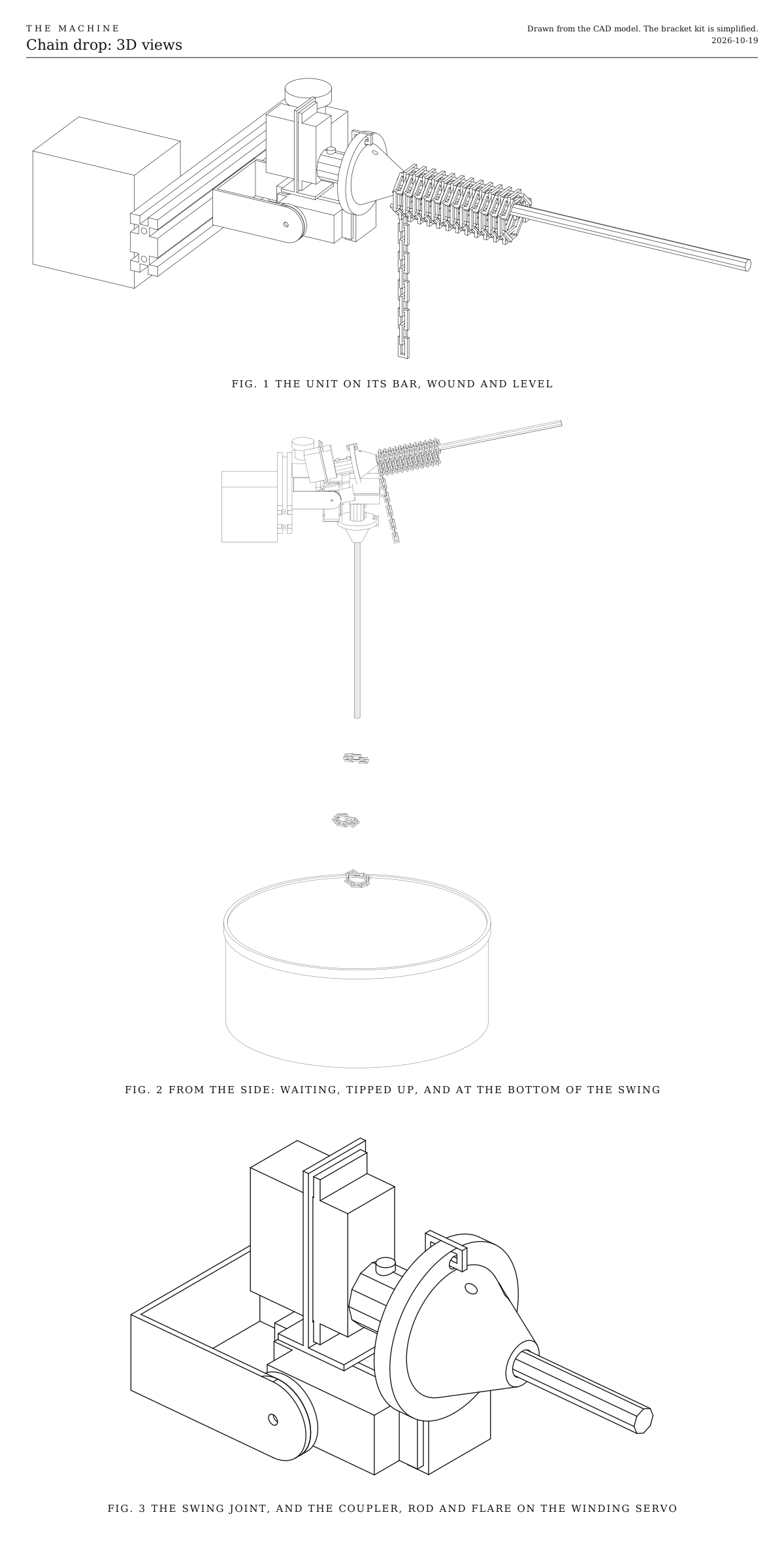
3D views. The unit on its bar; the swing from the side, waiting and at the bottom; and the swing joint up close. Drawn from the CAD model, with the bracket kit simplified.
Fig. 13D views. The unit on its bar; the swing from the side, waiting and at the bottom; and the swing joint up close. Drawn from the CAD model, with the bracket kit simplified.
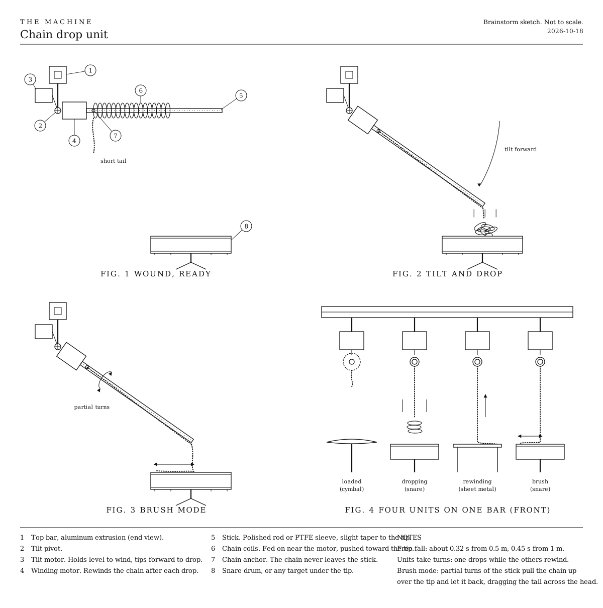
First sketch. The brainstorm, where the stick only tipped part way. The full swing replaced it; kept for its ideas.
Fig. 2First sketch. The brainstorm, where the stick only tipped part way. The full swing replaced it; kept for its ideas.

How it works

  • A chain is wound in loose coils on a rod. Two servos do the work: one swings the rod about a pivot, and one, made to spin continuously, turns the rod to wind the chain. Both sit in an off-the-shelf pan-and-tilt bracket kit bolted to the front of the bar, the winding servo right next to the pivot so it barely moves, and an aluminum servo coupler clamps the rod straight onto it. The only printed part is the flare at the rod’s base, which winds the chain on.
  • While it waits, the rod is tipped up a little, so the coils stay against its base.
  • On cue, the swing servo snaps the rod straight down at full speed, in about a quarter second, and stops it dead. Near the bottom of the swing the coils fly off the end and land on the target together, about a third of a second after the cue.
  • After a pause the rod swings back up to level. The chain’s last link is hooked through the flange of the flare at the base of the rod, so the chain never leaves the unit; it hangs from there down to the target. The winding servo spins the rod for about ten seconds and winds the chain back on. Each new coil forms on the flare and pushes the earlier ones along the rod, like rope on a capstan. Then the rod tips up to wait.
  • The swing servo holds its own angles, so the swing needs no switches. The winding servo runs for a set time, a little longer than your chain needs. Nothing senses a jam yet; Variations has a cheap way to count turns.
  • An ESP32 listens to the broadcast signal and drives both servos from two of its pins. It starts each swing early by the unit’s lead time, so the crash lands on the beat. It runs from the shared battery, and the stop button cuts the servos’ power itself.
  • The model and the files are one version, where we started: light steel chain on an 8 mm stainless steel rod, about 30 cm above a snare. The chain, the target, the rod and the drop are yours to choose, below.

Why it swings all the way down

The first sketch only tipped the stick part way. The coils then slide off at a shallow angle and fly forward, and how far depends on how slick the stick is that day. Swinging all the way to straight down changes that. The coils leave near the bottom of the swing, moving mostly downward, so they land close to the same spot whether the rod is slick or grippy. The swing speed moves that spot: slower lands it farther forward.

Notes

  • This is a first design, drawn but not yet built. Expect one round of fitting.
  • The bracket kit is drawn simplified, and kits differ. Expect to drill a hole or two.
  • The swing, landing and timing numbers come from a simple simulation of coils sliding on a swinging rod, not from a build. The test build settles them.
  • Costs in the ingredients are rough estimates for budgeting, not checked prices.
  • Firmware comes with the broadcast control system.

Parts

Ingredients

KindPartQtySourceEachFile
PrintedFlare, slides onto the rod against the coupler; new coils form on it, and the chain hooks through its flange1··STL
BoughtChain, about 1.2 mYour choice: see The chainWe started with light steel chain, about 2 mm wire and not welded, so a link opens with pliers. It weighs about 0.1 kg.1·$8.00
BoughtRod, 8 mm, about 300 mmYour choice: see The rodWe started with stainless steel.1·$6.00
BoughtMG996R servo, standard (turns about 180 degrees)This one swings the rod. Holding it level takes about 3 to 4 kg·cm, and the MG996R gives about 11 at 6 V. Sold in packs of four for about $19.1·$5.00
BoughtMG996R servo, continuous rotation (sold as 360 degrees)This one winds the chain. It has the same body, but it spins at a speed you set instead of going to an angle. You can also convert a standard one; see Variations.1·$8.00
BoughtPan-and-tilt servo bracket kit for MG995 and MG996R servos, a pack of two setsSet 1 makes the swing joint. Its U bracket bolts to the bar and stays still, and the swing servo turns inside it in set 1's servo bracket. Set 2's servo bracket holds the winding servo and bolts on top of set 1's. Set 2's U bracket is a spare.1·$12.00
BoughtAluminum servo shaft coupler, 25-tooth spline to 8 mm shaftClamps onto the winding servo's spline and grips the rod, so nothing printed has to hold the servo.1·$6.00
BoughtAluminum disc horn, 25 toothJoins the swing servo to the U bracket.1·$2.00
BoughtAluminum extrusion, 20 x 40 mm V-slot, 200 mmOr a length of a longer bar shared with other units.1·$5.00
BoughtM3 drop-in T-nuts for 20 mm V-slotBolt the U bracket to the bar's front face.2·$0.30
BoughtESP32 development board1·$6.00
BoughtBattery adapter for the shared power-tool platform, and a 5 V buck converterThe ESP32 and the relay run from the 5 V converter. The servos get their own, below.1·$15.00
BoughtThe listener parts every element carries, as on the Control pageA blade fuse holder and fuse (3 A for this element), a latching stop button with a spare contact, the status light, the number switches and their resistors. The stop switch under Choices has a plain two-pole switch in place of the stop button.1Link$12.00
BoughtMomentary push button, normally open, for the test buttonA short press plays each note once, and a long press relearns what the element can by itself. Any small panel button that closes while it's pressed will do.1·$1.00
BoughtBuck converter, adjustable, rated 8 A, for the servosSet it to 6 V. Two MG996Rs can each pull about 2.5 A as they start or stall, more than the ESP32's converter should carry.1·$7.00
BoughtRelay module, 5 V, high-level trigger, contacts rated 10 A, with a 10 kΩ resistorThe switch the servos' power goes through, after the stop button. The resistor holds it off while the ESP32 starts.1·$2.00
BoughtElectrolytic capacitor, 1000 µF, 10 V or moreAcross the servos' converter output, so a servo starting up doesn't pull the supply down.1·$0.30
BoughtSmall project box, for the electronicsYour choice: see The electronics1·$5.00
BoughtM5 screws and T-nuts for 20 mm V-slotFor the electronics box and the battery adapter.4·$0.30
BoughtHookup wire, 18 and 22 AWG, red, black and a signal color1·$5.00
BoughtM3 screws and nuts, a fewOne M3 x 16 with a nut for the flare's set screw, two into the T-nuts for the U bracket, and two with nuts to join the two servo brackets. The kit's own screws do the rest.1·$2.00
SalvagedSomething to land on, on its own standYour choice: see The targetThe target is not part of the build. We started with a snare drum.1··
Total$109.10

Tools

  • 3D printer, PETG
  • Soldering iron, for the wiring
  • Two pairs of pliers, to open and close a link
  • Small screwdrivers and hex keys
  • Drill, for a hole or two in the brackets
  • Hacksaw, to cut the rod and the chain to length
  • A servo tester, or the ESP32, to set the swing servo before fitting it
  • A phone, to record drops and listen back

Choices

Decisions that are yours to make. Where we started is the version in the 3D model and the ingredients: a starting point, not the right answer.

The chain

What falls on the target?

Light steel chain, about 2 mm wire, not weldedWhere we started

SoundBright, with more shimmer than crash

A link opens with pliers to hook onto the flare. Easy on the servos and on a drum head; tangles a little more easily

Steel link chain, 3 mm wire

SoundA denser, heavier crash with a metallic rattle in it

Sold by the meter at hardware stores and coils neatly, but usually welded, so join it to the flare with a small quick link

Heavy steel chain, 4 to 5 mm wire

SoundLoud, low and heavy, close to a dropped toolbox

Hard on drum heads, and more than an MG996R should swing. See A stronger swing, under Variations

Brass chain

SoundWarmer and rounder, with less hiss

Costs more; softer, so it wears and stretches

Length matters as much as metal. The chain has to reach the target from the base of the rod when the rod points straight down, with 20 to 50 cm left over to pile up; more pile, longer crash. For chain you can open with pliers, look for "jack chain" or chain sold as not welded. Any other chain joins the flare with a small quick link. Ball chain works too, but it tangles and doesn't coil as neatly.

The target

What does it land on?

A snare drumWhere we started

SoundA crash with a buzz from the snare wires underneath

The chain wears the head; an old drum or a practice head is fine

A crash or ride cymbal

SoundA long, washy ring after the hit

A cymbal tilts and swings on its stand, so the chain can slide off. Mount it flat and firm

A sheet of steel

SoundA harsh, industrial clang; thicker sheet rings lower

It is cheap and close to indestructible. Hang it from a corner, or lay it on foam

Found objects

SoundFrom a dull clunk to a bright ping, depending on what it is

A pan, a baking tray, a cajón, a board. The easiest to find and to swap

The rod

What does the chain wind on?

Stainless steel rod, 8 mmWhere we started

SoundA faint ring and scrape as the chain slides off and winds on

Stiff and slick, and the coupler grips it hard

Aluminum rod, 8 mm

SoundMuch the same, a little duller

The lightest on the swing; scratches easily, and a scratched rod grips the coils

Wooden dowel, 8 mm

SoundA dry, woody knock from the rod itself

Flexes a little under the chain at this thickness. Sand and wax it to keep it slick

The coupler's bore sets the rod's size, so buy the two to match; couplers come in 6 and 8 mm. A plastic rod this thin bends too much. For a different size, change ROD_R in the CAD script so the flare fits.

The drop

How far does the chain fall from the rod's tip to the target?

About 30 cmWhere we started

SoundA tight crash

The easiest to aim, and needs the least chain

50 cm to 1 m

SoundA bigger, heavier impact

Needs a longer chain, lands a little later, and is harder to aim

10 to 20 cm

SoundSofter, more of a pour than a crash

Lands soonest and most precisely

There is nothing to buy here. You set the drop by where you put the target.

The stop switch

What cuts the servos' power at the element?

Latching emergency-stop button, with a spare contactWhere we started

The red mushroom head anyone nearby knows to hit. It stays down until it's twisted to release, so the element can't start again by accident. Its main contact cuts the power and its spare contact tells the ESP32. About $8.

Two-pole power switch, a rocker or a toggle

Smaller, plainer and cheaper, about $2. One pole cuts the power and the other tells the ESP32, so it does the same job. It doesn't read as a stop to someone who doesn't know the Machine, and it switches back on as easily as off. Rate its contacts above what the element draws, as the button's are.

Keep the second pole either way. It tells the ESP32 the power was cut, so it swings the rod back to level and winds the chain on when the power comes back, as after a stop from the Bridge. Either way the relay stays, since it's how a stop from the Bridge reaches the element when no one is at it. A two-pole switch wires as the button does: one pole in place of the main contact, from 11 to 12, and the other in place of the spare contact, from 13 to 14.

Print

Material
PETG
Layers
0.2 mm
Walls
4
Infill
40%

There is one printed part, the flare. It fits any bed and prints without supports. PLA is fine too; it only feels the chain's pull.

The printed parts

  • Flare, slides onto the rod against the coupler; new coils form on it, and the chain hooks through its flange

    Which way up
    Flange down on the bed
    Supports
    None
    Time
    About an hour

    The bore, the chain's hole and the nut slot all come out clean this way up. The bore is drawn 0.3 mm over 8 mm; if your rod won't slide in, run an 8 mm drill through it.

    STL ↓

Assembly

  1. 1

    Bolt set 1's U bracket to the front face of the bar, its legs pointing forward, with two M3 screws into drop-in T-nuts.

  2. 2

    Power the standard servo from the ESP32 or a servo tester, and send it to the angle you'll call level.

  3. 3

    Fit the standard servo into set 1's servo bracket, and mount it between the U's legs the way the kit shows a tilt joint, horn screwed to one leg and the bushing on the other, with the bracket level. Here the U stays still and the servo's body turns.

    TrickyKits differ. If something touches before the end of the swing, refit the horn one spline tooth over, or file the corner that touches.

    CheckThe servo and its bracket turn about 105 degrees, from a little above level to pointing a quarter turn down, without touching the U or the bar.

  4. 4

    Bolt set 2's servo bracket on top of set 1's, and fit the continuous-rotation servo in it standing up, with its spline pointing forward, where the rod will go.

    TrickyThe two brackets' holes may not line up. Drill a pair where they meet.

  5. 5

    Push the coupler onto the winding servo's spline and tighten its clamp screw.

  6. 6

    Push your rod into the coupler's other end and tighten the screws that grip it.

    TrickyThe coupler's bore and your rod have to match. A rod even a little undersize wobbles however hard you tighten it.

  7. 7

    Slide an M3 nut into the slot in the side of the flare, slide the flare onto the rod against the coupler, and tighten an M3 screw down through the nut onto the rod.

    CheckThe rod runs true when the winding servo turns it slowly.

  8. 8

    Open the last link of your chain with pliers, slip it through the hole near the rim of the flare's flange and around the rim, and squeeze it shut. Let the rest hang.

    CheckThe link closes with no gap the chain could slip out through.

  9. 9

    Fix the electronics box and the battery adapter to the bar, as the Mounting tab shows.

  10. 10

    Wire it as the Wiring tab shows, from the battery outward. The fuse comes first; the servos' power goes through the stop button and the relay to their own 6 V converter.

    TrickySet both converters before connecting anything, the ESP32's to 5.0 V and the servos' to 6.0 V. Both servos' cables flex on every swing, so tie them down with a loose loop at the pivot.

  11. 11

    Run the winding servo slowly and watch the coils form on the flare and walk along the rod.

    TrickyThis is the least certain part of the design. If the coils pile up at the base instead of walking along, see Tuning.

    CheckThe coils lie side by side without riding up on each other.

  12. 12

    Time how long your chain takes to wind on fully, and set the unit's winding time to that plus about a fifth.

  13. 13

    Set your target under the rod's straight-down position, your drop below its tip. Try a few slow swings and watch where the coils go before running it at speed.

    TrickyKeep hands and faces out of the swing once it runs. The snap is fast, and the chain is thrown a little.

Wiring

The fuse comes first, right after the battery. The ESP32 runs from the 5 V converter. The servos get their own 6 V converter, sized for the current they pull as they start, and its power comes through the stop button and then the relay, so either one cuts it. The servos' ground joins the ESP32's, so their signals share a reference. The status light, the number switches and the battery reading are wired the same way on every element, so they're on the Control page, not here.

Wiring · Chain Drop
PowerSignalGround, all joinedPins drawn faint are left empty.

Wire list

  1. Battery adapter, +

    Fuse, 3 A, in

    PowerRed, 16 AWG

    As short as the adapter allows. Nothing connects ahead of the fuse.

  2. Fuse, 3 A, out

    5 V converter, IN+

    PowerRed, 22 AWG

  3. Fuse, 3 A, out

    Stop button, 11

    PowerRed, 18 AWG

  4. Stop button, 12

    Relay module, COM

    PowerRed, 18 AWG

    The stop button's main contact opens when pressed, cutting the servos' power itself, so a program that hangs can't ignore it.

  5. Relay module, NO

    6 V converter, 8 A, IN+

    PowerRed, 18 AWG

  6. 6 V converter, 8 A, OUT+

    Swing servo, MG996R, red +

    PowerRed, 18 AWG

    Only once the converter is set to 6 V.

  7. 6 V converter, 8 A, OUT+

    Winding servo, MG996R 360°, red +

    PowerRed, 18 AWG

  8. Capacitor, 1000 µF, +

    6 V converter, 8 A, OUT+

    PowerThe capacitor's own leg

    Solder its legs straight onto the converter's output terminals. The stripe on its side marks the − leg.

  9. 5 V converter, OUT+

    ESP32 board, 5V

    PowerRed, 22 AWG

    Only once the converter is set to 5 V.

  10. 5 V converter, OUT+

    Relay module, VCC

    PowerRed, 22 AWG

  11. Battery adapter, −

    5 V converter, IN−

    GroundBlack, 22 AWG

  12. Battery adapter, −

    6 V converter, 8 A, IN−

    GroundBlack, 18 AWG

  13. 6 V converter, 8 A, OUT−

    Swing servo, MG996R, brown −

    GroundBlack, 18 AWG

  14. 6 V converter, 8 A, OUT−

    Winding servo, MG996R 360°, brown −

    GroundBlack, 18 AWG

  15. Capacitor, 1000 µF, −

    6 V converter, 8 A, OUT−

    GroundThe capacitor's own leg

  16. 5 V converter, OUT−

    ESP32 board, GND

    GroundBlack, 22 AWG

  17. 6 V converter, 8 A, OUT−

    ESP32 board, GND

    GroundBlack, 22 AWG

    Joins the servos' ground to the ESP32's. Without it the servos can't read their signals reliably.

  18. Relay module, GND

    ESP32 board, GND

    GroundBlack, 22 AWG

  19. Resistor, 10 kΩ, 2

    ESP32 board, GND

    GroundThe resistor's own leg

  20. Stop button, 14

    ESP32 board, GND

    GroundBlack, 22 AWG

  21. Test button, 2

    ESP32 board, GND

    GroundBlack, 22 AWG

  22. ESP32 board, GPIO 25

    Swing servo, MG996R, orange signal

    SignalAny color, 22 AWG

    The swing servo goes to the angle the pulse width sets.

  23. ESP32 board, GPIO 26

    Winding servo, MG996R 360°, orange signal

    SignalAny color, 22 AWG

    The winding servo turns at the speed the pulse width sets, and stops at 1.5 ms.

  24. ESP32 board, GPIO 33

    Relay module, IN

    SignalAny color, 22 AWG

  25. Resistor, 10 kΩ, 1

    Relay module, IN

    SignalThe resistor's own leg

    Holds the relay off while the ESP32 starts, when its pins float, so neither servo twitches.

  26. Stop button, 13

    ESP32 board, GPIO 13

    SignalAny color, 22 AWG

    The stop button's spare contact, so the ESP32 knows it's been pressed.

  27. Test button, 1

    ESP32 board, GPIO 15

    SignalAny color, 22 AWG

    The test button. The ESP32's own pull-up holds the pin high until it's pressed. The board reads GPIO 15 as it starts, but only to choose whether to print, so holding the button then does no harm.

Get these right

Set the converters first
Most converters come set higher than you want. Turn each one's screw with the battery in and a multimeter on its output, the ESP32's to 5.0 V and the servos' to 6.0 V, and only then connect anything to them. More than about 6 V destroys the ESP32, and more than about 7 V the servos.
The servo plugs
Each servo's three wires are brown for −, red for + and orange for the signal. Plug them onto header pins, or cut the plugs off and solder. Swapping + and − destroys a servo.
Stopping the winding servo
It turns at a speed rather than going to an angle, and a 1.5 ms pulse should hold it still. If it creeps at 1.5 ms, turn the small trim screw in its side until it stops.
The pins
Any free ESP32 pins will do, except 0, 2, 5 and 12, which the board reads as it starts, and 34 to 39, which can only read. The board reads 15 as it starts too, but only to choose whether to print, so 15 carries the test button on every element. If you use others, the firmware needs to know.

Mounting

Everything fixes to the bar with T-nuts and screws, so any part can slide along it or come off with a hex key. Only the servos move; the electronics, the stop button and the battery stay put on the bar, away from the swing.

The bar
A 200 mm length of 20 x 40 V-slot, standing on its narrow edge, held at both ends by whatever frame or stands carry your bars. Its height sets the drop.
The swing joint
Set 1's U bracket, flat on the bar's front face, with two M3 screws into drop-in T-nuts in the face's two slots. Everything else that moves hangs from it.
The electronics
In the project box on the bar's front face, beside the unit and clear of the swing, on two M5 screws into T-nuts. The servos' cables loop from the box to the pivot.
The stop button
On top of the electronics box, where a hand finds it without reaching past the swing.
The battery
The adapter on the bar's back face, at the other end from the box, on two M5 screws into T-nuts, so the pack slides on and off without reaching past the swing.
The target
On its own stand under the pivot, not fixed to the bar, so you can move it until the chain lands in the middle.
The wires
Clip-in slot covers hold the wires inside the bar's slots, out of sight and out of the chain's way.

The electronics

Hidden in a box, or on show?

Closed boxWhere we started

A small project box, bought or printed, on the bar. Tidy, and safe from a thrown chain, but it hides the electronics.

Open plate

The boards on standoffs on a flat plate on the bar, with the wires dressed along the slot. The electronics become part of the look. It wants neat wiring, and nothing guards it from the chain.

DIN rail

A short length of 35 mm DIN rail on T-nuts, with each board in a snap-on holder. It looks like a control panel, and any board comes off with a flick. The holders add a few dollars.

Whichever you pick, keep the stop button on the outside, where anyone can reach it.

Tuning

Tuning

The test button
A short press drops the chain once, about a second after you let go, then swings the rod back and winds the chain on. A long press does nothing here, since nothing on it senses where the chain is: it winds by time. It works only while the element is resting, with no Bridge in range or with the Bridge holding it silent. While it plays or is stopped, the button does nothing. A stop ends a test at once, and pressing again ends one early. The winding time and the lead are still measured by hand.
Snap, or lower
We start with a snap. The ESP32 sends the swing servo straight to its down angle, so it swings at full speed, about a quarter second, and stops itself dead at the bottom. That gives a sharp hit, right on cue. Easing the swing over a second or more softens it into more of a pour, and lands the chain farther forward. It is a playing choice you can change from one drop to the next.
Where it lands
Watch where the chain hits. With a snap and a 30 cm drop, it should land within a few centimeters of the spot under the pivot; with a 60 cm drop, within about 10 cm. A slower swing lands it farther forward, about 10 cm for every extra half second. Move the target until the chain lands in the middle.
One crash, or a roll
Listen for one hit against a rattle that runs on. The coils should arrive within about a tenth of a second of each other. For a tighter crash, use less chain, so there are fewer coils; for a longer roll, use more.
On the beat
If the crash lands after the beat, start the swing earlier. Record a few drops on a phone and listen back. With a snap and a 30 cm drop, expect it about 0.3 to 0.4 seconds after the cue; with a one-second swing, about 0.8 seconds.
Winding time
The winding servo runs for a set time, not a set number of turns, and it slows as the battery runs down. If the end of the chain is still hanging when it stops, wind longer. Extra time is harmless; once the chain is on, the extra turns just spin the coils with the rod.
The rewind scrape
Winding drags the chain off the target, which makes a sound of its own. Wind slowly for a long scrape you can use, or quickly to get it out of the way. If the pile is choking the next hit, let the rewind start sooner.
Coils that creep or cling
While it waits, the rod tips up about 12 degrees so the coils stay against the base; if they creep along anyway, tip it up more. If they cling to the rod at the bottom of the swing, they were wound on too tight, so run the winding servo backward for a moment before each drop.
Coils that pile up
Wind with the rod level. If the coils pile up at the base instead of walking along, wind more slowly, or tip the rod down a few degrees while it winds; if they run ahead and slip off the end, tip it up.

Variations

A longer or shorter rod
A longer rod lets the coils slide farther and fall harder, and lands them a little farther forward. A shorter rod drops sooner and tighter. Keep the coils to the first half of the rod; each takes roughly 11 cm of chain and 1 cm of rod. Past about 40 cm, or with a heavy rod, the swing servo needs more strength. Change ROD_LEN in the CAD script to redraw it.
A stronger swing
For heavy chain or a long rod, use a stronger servo of the same size, 25 to 35 kg·cm. Check its height first; the bracket fits servos about 36 to 37 mm tall, and some stronger ones are taller.
Counting turns
A small magnet in the flare's flange and a Hall-effect sensor (about $1) let the ESP32 count turns instead of timing them. The wind stays exact as the battery runs down, and a jam can light the status light.
Converting a standard servo
A spare standard MG996R can be made to spin. Open it, cut the small stop off its output gear, and free its position sensor from the output shaft, set to its middle. Fiddly, but free if you have one.
A gate at the tip
A third servo holds a paddle over the rod's end until the rod points straight down, then flicks it aside. The coils fall from rest, straight down, the moment the gate opens, so the timing and the aim get tighter, at the cost of one more servo and a light arm out to the tip.
Brush mode
Leave the chain unwound, hanging from the base with its tail on the drum head, and have the winding servo turn the rod slowly back and forth. The chain winds up a little and pays out again, dragging its tail across the head like a brush. The anchor sits off the rod's center, so the chain swirls a little as well.
Several on one bar
Two to four units can share one control set on one bar and play as a small kit. They share the ESP32, the battery adapter and 5 V converter, the fuse, the stop button and relay, the status light and number switches, and the electronics box, about $45 in all. Each unit still needs its own two servos, bracket kit, coupler, rod, chain and flare, about $50. Two units come to about $155 and four to about $265, against $215 and $430 built separately. The bar takes one number per unit, in a row from the one its switch sets, so the show computer can give each unit its own rhythm. They can take turns, one dropping while the others rewind, which gets past the ten-second rewind, and a different chain, rod and target on each widens the kit. Space them for the targets: about 40 cm apart for a snare each, or 10 to 15 cm apart over one sheet of steel or a pair of drums.
Several on one bar, wiring and power
Each servo needs its own signal pin. Two units fit on the ESP32's own pins, GPIO 25 and 26 for the first and 27 and 32 for the second, but that takes its last free pins once the status light and number switches are in. From three units up, a 16-channel servo board (PCA9685, about $5) carries every servo signal on two pins, GPIO 21 and 22; feed the servos' power from a separate bus, not through the board. The relay and the stop button stay single and cut every servo at once. The servos' 6 V supply grows with them: one 8 A converter and capacitor for every two units, or a single 20 A converter for four. Raise the fuse to 5 A for three or four units. The swing servos draw current just holding their rods up, so expect a 4 Ah pack to last a couple of hours of playing, and check it. Each snap jolts the bar, so check that the neighbors' coils stay put while they wait.