Skip to content

The Machine · Recipes

Catapult

Design stage

Updated 2026-10-19

A counterweighted arm lobs a wooden ball at a hanging plate. A snail cam lets the arm go and winds it back down, and the ball rolls home under the arm to be thrown again.

Loading the model

Drag to turn · scroll to zoom

Printed

3DWhere we started. This is one version of it. A carbon arm with ten washers for a counterweight throws a 25 mm wooden ball about 85 cm at a hanging steel plate, and a snail cam on a slow gearmotor lets it go and winds it back. Press Play to watch the weight land on the stop block, the ball strike the plate and roll home, and the gate load the next ball as the arm comes back down. The swing and the flight are worked out from the parts' weights, not drawn by hand. Printed parts are drawn in orange; everything else is bought.

Overview

Cost, roughly
About $180
Printing
About 10 hours, in seven parts
Building
A weekend
Difficulty
Involved

Anatomy

1
Energy source
The counterweight, raised on the arm's short end
2
Control
A snail cam on a slow gearmotor; turning it past its step lets the arm go
3
Sounding body
The plate the ball strikes, and the stop block the weight lands on
4
Reset
The cam winds the arm back down, the ball rolls home down the chute, and the arm loads the next one as it cocks
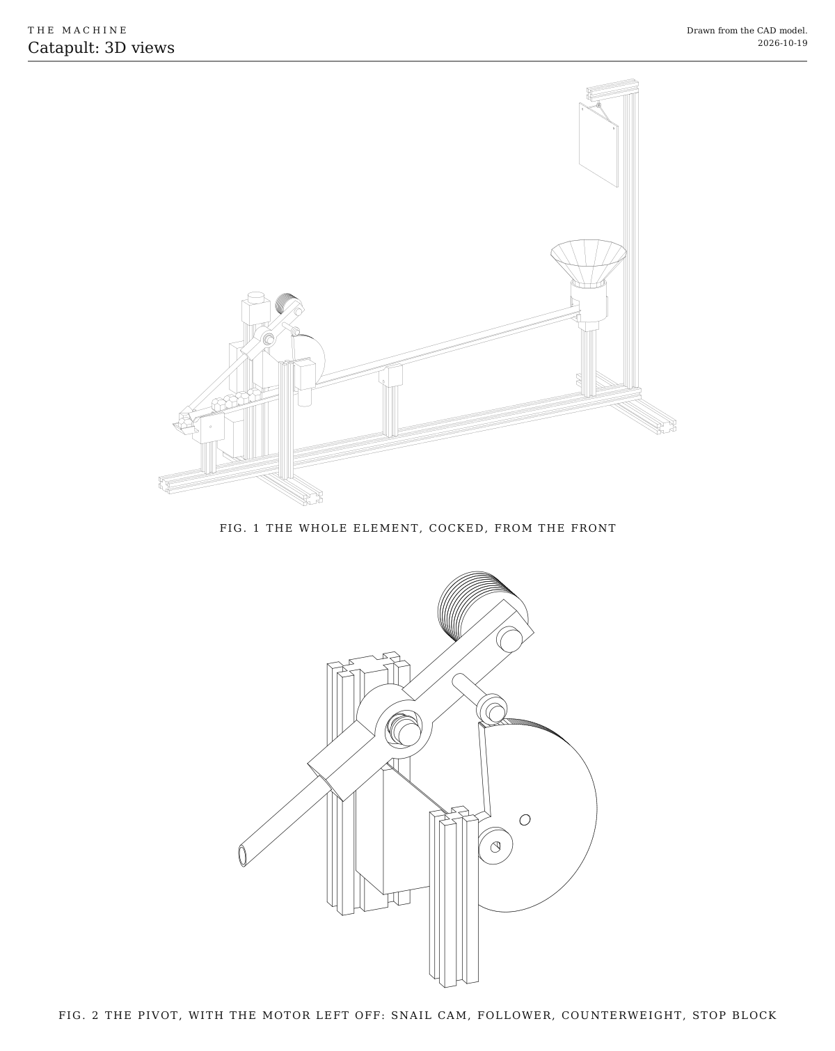
3D views. The whole element cocked, and the pivot up close with the motor left off so the snail cam shows. Drawn from the CAD model.
Fig. 13D views. The whole element cocked, and the pivot up close with the motor left off so the snail cam shows. Drawn from the CAD model.
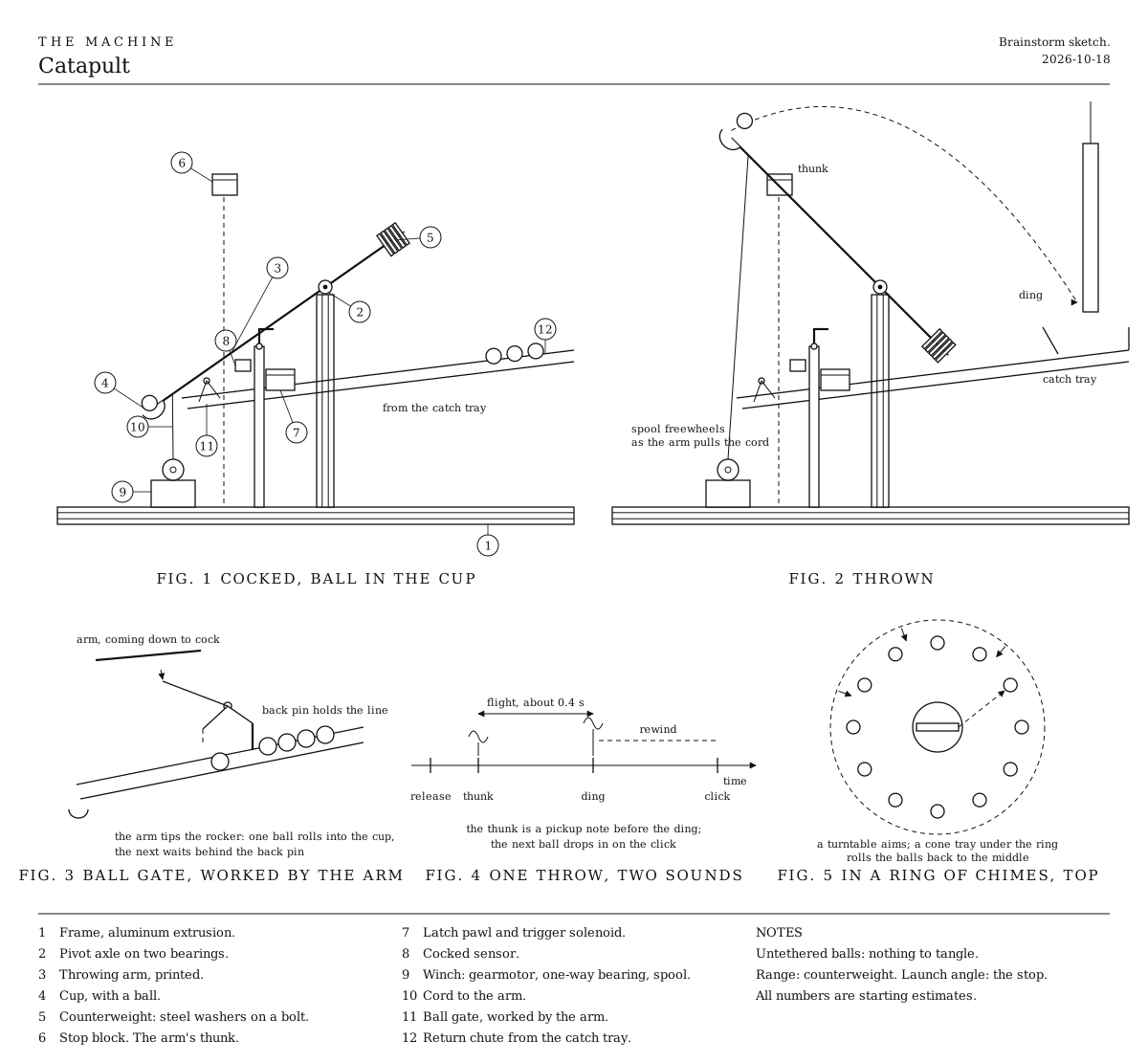
First sketch. The idea as first drawn, cocked and thrown, with the ball gate, one throw making two sounds, and the catapult in a ring of chimes. It used a winch and a solenoid latch where the model has a snail cam.
Fig. 2First sketch. The idea as first drawn, cocked and thrown, with the ball gate, one throw making two sounds, and the catapult in a ring of chimes. It used a winch and a solenoid latch where the model has a snail cam.

What it does

  • It lobs. The ball travels in a slow, high arc the audience can follow, about 85 cm to a hanging steel plate.
  • Nothing is tied to the ball. There’s no tether to tangle and no reel to fault. Five balls circulate, so the note rate is set by how fast the arm re-cocks.
  • One throw makes two sounds. The counterweight lands on its stop block with a thunk, and 0.39 s later the ball strikes. The flight sits between them like a pickup note.
  • The mechanism is the show. A cam turns, a weight drops, an arm swings, a ball flies and strikes, rolls home under the arm and is loaded again. Every step is visible, and the ball’s whole path is one loop you see side-on.

It asks for some care in return. The balls need a funnel and a path home, the gate needs setting, and it’s big and loud for one note.

How it works

  1. The arm waits, cocked. The snail cam has lifted the counterweight on the short end of the arm, and holds it there. Its worm gearbox can’t be pushed backward, so it holds with the power off. A ball sits in the cup at the bottom of the arm’s swing, at the end of the chute.
  2. The cam turns past its step. On the cue the motor turns the cam the last few degrees. The follower bearing on the arm’s short end drops off the cam’s step, and nothing holds the arm.
  3. The weight drops and the arm swings up. About 0.2 s later the washers land on the hardwood stop block. The arm stops 45 degrees above level and the ball flies on, at about 3 m/s.
  4. The ball strikes the plate. It lands 0.39 s after the thunk, drops into the funnel below the plate, and falls through its spout into the top of the chute.
  5. The cam winds the arm back down. It keeps turning, comes round under the follower and lifts the counterweight again over most of a turn. Meanwhile the thrown ball rolls home down the chute, under the arm, and joins the end of the line.
  6. The arm loads the next ball. In its last two degrees the arm presses a plunger that tips the gate’s rocker. The front pin drops and the first ball rolls off the chute into the cup; the back pin rises and holds the rest. The cam parks, cocked, until the next cue.

The motor only ever turns one way, one turn per throw, about 2.4 s at 25 rpm.

The stop block

  • The block takes the arm’s whole swing on every throw, so it has to be solid, but it doesn’t have to be quiet. A wood block, a cowbell or a small drum turns it into an instrument.
  • Its slope is where the arm stops, and so the launch angle. Move it to change both.
  • The arm must not bounce off it and swing back into the ball’s path. A dense block, bolted tight, keeps the bounce small.

Getting the balls home

  • The ball’s whole path is one loop in a single plane: out over the top in the air, back underneath along the chute. The arm swings 28 mm behind that plane, and the cup reaches across to hold the ball in it.
  • The funnel under the plate catches the ball, and its spout drops it into the top of the chute. From there it’s downhill all the way, about 4 degrees, taking about 2 s.
  • The gate passes exactly one ball each time the arm is cocked. An empty cup still makes the thunk with nothing after it. That may be useful.
  • A few balls will bounce out over a long performance. Keep a spare, and fence the target with a lip or netting if it happens often.

The numbers

These come from the model, worked out from the parts’ weights and shapes. The bench will correct them.

Where we started
Ball 25 mm hardwood, about 6 g
Throw About 85 cm, to a plate about 10 cm above where the ball leaves the cup
Launch 45 degrees, about 3 m/s
Arm About 420 g with the ball, which sits 225 mm from the pivot
Counterweight Ten 40 mm washers, about 280 g, 75 mm from the pivot
Cue to thunk About 0.24 s, the cam’s last few degrees and then the swing
Thunk to strike About 0.39 s, the ball’s flight
Rate At most one throw every 2.4 s, the cam’s one turn

A few things follow from these.

  • The arm and the cup weigh far more than the ball, and they’re thrown too. A lighter arm and cup throw farther for the same counterweight.
  • Fire about 0.63 s ahead of the beat to land the strike on it. The thunk then lands 0.39 s ahead of the beat.
  • Two catapults taking turns would double the rate.

Sensing and faults

  • The Hall sensor sees the magnet in the cam only when the cam is parked, with the arm cocked. It’s the one sign the catapult is ready.
  • A turn takes too long. If the magnet hasn’t come round within about four seconds, something is jammed. Stop the motor and hold.
  • It never fires from a fault. A fault shows as a pattern on the status light, since elements only listen and can’t report over the radio.

References

  • Mangonel and trebuchet. These are throwing engines with a swinging arm. The mangonel stops its arm on a crossbar; the trebuchet uses a falling counterweight.
  • Snail cam. The same shape drops the hammers in music boxes and automata, and lifts and drops a trip hammer’s head.
  • Wintergatan Marble Machine. A hand-cranked machine that plays music by dropping marbles onto instruments, with the marbles running home on tracks. Gravity does the playing.

Notes

  • This is a first design, drawn from the model rather than a built one. Expect one round of fitting, above all at the gate.
  • The swing and the flight in the 3D model are worked out from the parts’ weights, with a guess for how much the arm bounces off the block. A test build will give the real figures.
  • Costs in the parts list are rough estimates for budgeting, not checked prices. They add up the version we started with.
  • The firmware’s job is small. It listens for Control, the one broadcast signal every element hears. On a cue it runs the cam until the magnet comes round again, then brakes, and it fires about 0.63 s early so the strike lands on the beat.

Parts

Ingredients

KindPartQtySourceEachFile
PrintedHub, turns on the axle and holds the tube, the counterweight and the follower1··STL
PrintedCup, slips onto the tube's end and holds the ball1··STL
PrintedSnail cam1··STL
PrintedGate block, holds the chute's low end, the rocker and the plunger1··STL
PrintedGate rocker1··STL
PrintedChute cradle, holds the chute partway along1··STL
PrintedChute head, holds the chute's top end and the funnel's spout1··STL
BoughtAluminum extrusion, 20 x 40 mm V-slot, 1000 mm, for the base barV-slot has V-shaped grooves along each face. T-nuts slide in them, so anything bolted on can slide to a new place.1·$18.00
BoughtAluminum extrusion, 20 x 40 mm V-slot, 300 mm, for the feet2·$7.00
BoughtAluminum extrusion, 20 x 40 mm V-slot, 270 mm, for the upright the arm turns on1·$7.00
BoughtAluminum extrusion, 20 x 20 mm V-slot, about 1.25 m in all, for the posts and the target armCut into six: 225 mm for the motor post, 76, 114 and 143 mm for the chute's three posts, 580 mm for the target post and 100 mm for the target arm.1·$14.00
BoughtCorner brackets for 20 mm V-slot, with screws and T-nuts16·$1.00
BoughtM8 x 70 bolt, washers and a locking nut, for the axle1·$2.00
BoughtSpacers for M8, 12 mm and 10 mm longThe 12 mm one goes between the hub and the upright, the 10 mm one inside the hub between its bearings.1·$1.00
BoughtBall bearings, 608 size (8 mm bore, 22 mm across), the kind in skateboard wheels2·$1.00
BoughtCarbon fiber tube, 10 mm outside, 8 mm inside, 200 mmYour choice: see The arm1·$5.00
BoughtM8 x 60 bolt and nut, and ten steel washers 40 mm across and 3 mm thick, for the counterweightYour choice: see What throws itSold as M8 repair or penny washers. Ten weigh about 280 g.1·$6.00
BoughtM5 x 70 bolt and nut, a 625 bearing (5 mm bore, 16 mm across) and a 40 mm spacer, for the followerThe bearing rides the cam's edge. A length of 8 mm aluminum tube does for the spacer.1·$3.00
BoughtWorm gearmotor, 24 V, about 30 rpm, with its L-bracket (JGY-370 or similar)Your choice: see How it cocks and firesA worm gearbox can't be turned backward by its load, so it holds the arm cocked with no power. On the pack's 18 to 20 V it turns about 25 rpm.1·$14.00
BoughtDRV8871 motor driver boardYour choice: see How it cocks and fires1·$8.00
BoughtHall sensor board (A3144) and a 6 x 3 mm magnetYour choice: see How it cocks and firesThe magnet goes in the cam. The sensor sees it when the cam is parked, cocked.1·$3.00
BoughtTwo M3 x 12 screws for the gate's pins, an M4 x 20 for its plunger, an M3 x 30 for the rocker's pivot, and an M5 x 25 bolt and nut to weight the rockerYour choice: see How the next ball is fed1·$2.00
BoughtAluminum angle, 20 x 20 x 1.5 mm, 870 mm, for the chuteYour choice: see The chute1·$6.00
BoughtWide-mouth canning funnel, about 14 cm acrossIts spout has to pass a 25 mm ball easily. A kitchen funnel's narrow spout won't.1·$5.00
BoughtSteel plate, about 140 x 120 x 3 mmYour choice: see The target1·$5.00
BoughtBraided cord and a small screw eye, to hang the target1·$2.00
BoughtHardwood balls, 25 mmYour choice: see The ballFive circulate; keep one spare for the one that escapes.6·$0.60
BoughtM5 screws, T-nuts and washers, assortedStop block (two M5 x 45), motor bracket, and one screw into a T-nut in each post for the gate block and the chute holders.1·$6.00
BoughtESP32-S3 development board1·$6.00
BoughtBattery adapter for the shared power-tool platform, and a 5 V buck converterThe gearmotor runs from the battery, through the fuse, the stop button and the relay. The ESP32 and the sensor take 5 V.1·$15.00
BoughtThe listener parts every element carries, as on the Control pageA blade fuse holder and 2 A fuse, a latching stop button with a spare contact, the status light, the number switches and their resistors. The stop switch under Choices has a plain two-pole switch in place of the stop button.1Link$12.00
BoughtMomentary push button, normally open, for the test buttonA short press plays each note once, and a long press relearns what the element can by itself. Any small panel button that closes while it's pressed will do.1·$1.00
BoughtRelay module, 5 V, high-level trigger, contacts rated 10 AThe switch the motor's power goes through.1·$2.00
BoughtElectrolytic capacitor, 100 µF, 35 VAcross the driver's motor supply, to soak up the spikes the motor sends back.1·$1.00
BoughtSmall project box, for the electronicsYour choice: see The electronics1·$5.00
SalvagedHardwood block, about 75 x 36 x 75 mm, for the stopYour choice: see The stop blockCut a 45 degree slope across one top corner, where the washers land, as in the model.1··
Total$184.60

Tools

  • 3D printer, PETG
  • Hex keys, 2.5, 3 and 4 mm
  • A drill, with 8.5 mm and 4 mm bits, and a small file
  • A fine saw, for the tube and the aluminum angle
  • Soldering iron, for the wiring
  • A multimeter, to set the 5 V converter
  • A kitchen scale, to weigh the counterweight
  • A phone that films in slow motion, to watch the release

Choices

Decisions that are yours to make. Where we started is the version in the 3D model and the ingredients: a starting point, not the right answer.

The ball

What does it throw?

Hardwood ball, 25 mmWhere we started

SoundA warm click on the plate, and a soft rumble down the chute

About 6 g. Cheap craft balls, safe on every target, and light enough for this arm to throw well.

Glass marble, 25 mm

SoundA bright, glassy tick, and a clatter on the way home

About 20 g, three times the wood, so it needs a much heavier counterweight to reach the plate. Can chip against steel.

Steel ball, 25 mm

SoundThe loudest and most metallic strike

About 64 g, ten times the wood. This arm won't throw it far; it wants a heavier build all round.

Rubber ball, 25 mm

SoundA dull thud, and near silence in the chute

Bounces unpredictably, so more balls miss the funnel. Fence the target with a lip or netting.

The cup, the chute and the gate are drawn for 25 mm balls. A heavier ball flies shorter on the same counterweight, so add washers until it reaches.

The target

What does the ball strike?

Hanging steel plateWhere we started

SoundRings long and bright, like a bell

A hardware-store offcut, 2 to 4 mm thick; thicker rings lower and longer. A big face, so aim matters little, and it hangs right over the funnel.

Chime tube

SoundA clear pitch that sings on

A tuned aluminum tube hung where the plate is. It's narrow, so the throw has to be set to hit it.

Frame drum, tilted

SoundA round thump

A big target. Tilt the head toward the catapult so the ball drops off it into the funnel.

Wood or temple block

SoundA dry knock

Hang it on a cord like the plate. With a hardwood stop block, both sounds are wood.

Whatever you hang has to let the ball fall straight down into the funnel.

The stop block

What does the counterweight land on?

Hardwood blockWhere we started

SoundA solid thunk, landing as you see the weight drop

Maple, oak or beech. It takes the arm's whole swing on every throw, so it has to be dense.

Cowbell or agogo bell

SoundA clank that rings on under the strike

Bolt it solidly under the weight. The washers will dent thin metal over time.

Practice pad or small drum

SoundA softer, drummy thump

Needs a stiff mount under it, or the arm bounces and the throw varies.

Rubber or leather pad on the block

SoundNearly silent, so you hear only the strike

The gentlest on the arm. The thunk is half of the element's sound, so this gives it up.

Raising or lowering the block changes where the arm stops, and so the launch angle.

The arm

What carries the cup?

Carbon fiber tube, 10 mmWhere we started

SoundSilent itself

The lightest and stiffest, so more of the weight's drop goes into the ball. Cut it with a fine saw, wrapped in tape so it doesn't splinter.

Wooden dowel, 10 mm

SoundA soft knock as the arm stops

Cheap and warm-looking, but about twice the weight, so it needs a washer or two more.

Aluminum tube, 10 mm

SoundRings faintly at every stop

Stiff and cheap. The ring can be a feature or a buzz under the strike.

The hub and the cup are drawn for a 10 mm tube.

What throws it

What stores the energy?

Fixed counterweightWhere we started

SoundThe weight's drop is what you see, and it lands with the thunk

Washers on a bolt, so changing the range is adding or taking one away. Simple, and the same every throw.

Hinged counterweight

SoundA heavier clank as the weight swings on its hanger

As on a trebuchet. More of the drop reaches the ball, so it throws farther for its weight, but the weight swings about after the stop. Needs a hanger in place of the bolt.

Elastic cord

SoundQuiet, with a snap

Surgical tubing from the short arm down to the base. Compact and quick, but rubber tires over a long show, so the range drifts.

How it cocks and fires

What winds the arm down and lets it go?

Snail camWhere we started

SoundA soft whirr as it winds, then the drop

One motor does both, with no cord or latch. The worm gearbox holds it cocked with the power off. The release comes a steady few hundredths of a second after the motor moves, which the firmware allows for.

Winch and latch

SoundA whirr, a click as the latch catches, and the solenoid's tick on release

The crispest release, exactly on command. Two actuators and a sensor, the cord has to stay out of the swing, and a free-spinning spool can tangle like a fishing reel.

Servo and latch

SoundA servo's buzz while it holds

The cheapest and simplest to wire. A hobby servo pushes the arm down and swings clear, and a solenoid latch lets it go.

How the next ball is fed

What lets one ball into the cup?

Gate worked by the armWhere we started

SoundA quiet click as the pins swap

No extra motor. The arm presses a plunger in its last two degrees of cocking.

Servo gate

SoundA servo's whirr

Feeds only when told, so the catapult can throw empty and play the thunk on its own. One more part to wire.

The chute

What do the balls roll home in?

Aluminum angleWhere we started

SoundA rolling rumble on the way home

Cheap and straight. Laid corner down, it makes a V the balls run in.

Wooden channel

SoundQuieter and warmer

Cove molding, or a strip with a V cut along it. The holders need opening out to fit.

Clear tube, slotted

SoundNearly silent, and you see the balls inside

An acrylic tube 32 mm inside, with a slot cut along its underside for the gate's pins.

The stop switch

What cuts the motor's power at the element?

Latching emergency-stop button, with a spare contactWhere we started

The red mushroom head anyone nearby knows to hit. It stays down until it's twisted to release, so the element can't start again by accident. Its main contact cuts the power and its spare contact tells the ESP32. About $8.

Two-pole power switch, a rocker or a toggle

Smaller, plainer and cheaper, about $2. One pole cuts the power and the other tells the ESP32, so it does the same job. It doesn't read as a stop to someone who doesn't know the Machine, and it switches back on as easily as off. Rate its contacts above what the element draws, as the button's are.

Keep the second pole either way. It tells the ESP32 the power was cut, so it turns the cam on to its magnet before it throws again when the power comes back, as after a stop from the Bridge. Either way the relay stays, since it's how a stop from the Bridge reaches the element when no one is at it. A two-pole switch wires as the button does: one pole in place of the main contact, from 11 to 12, and the other in place of the spare contact, from 13 to 14.

Print

Material
PETG
Layers
0.2 mm
Walls
4
Infill
40%

Every part fits a 150 mm bed. PETG takes the knock of every throw; PLA is fine for a first try. Print the hub and the cam first, and try the bearings and the motor shaft in them before printing the rest.

The printed parts

  • Hub, turns on the axle and holds the tube, the counterweight and the follower

    Which way up
    Flat on its front face, the side the counterweight bolt's head goes on
    Supports
    None
    Time
    About 2 hours

    The bearings are a press fit. If one's too tight, sand the pocket a little; if loose, a dab of glue on its outer ring holds it. Keep glue off the inner ring.

    STL ↓
  • Cup, slips onto the tube's end and holds the ball

    Which way up
    On its side, the front wall down
    Supports
    Under the tube's socket only
    Time
    About 30 minutes

    Kept thin on purpose. Every gram here is thrown along with the ball.

    STL ↓
  • Snail cam

    Which way up
    Flat, the boss up
    Supports
    None
    Time
    About 2 hours

    The bore fits the motor's 6 mm D-shaped shaft. An M3 nut drops into the boss's side for the set screw.

    STL ↓
  • Gate block, holds the chute's low end, the rocker and the plunger

    Which way up
    Base down
    Supports
    Under the plunger's guide only
    Time
    About 2 hours
    STL ↓
  • Gate rocker

    Which way up
    On its side
    Supports
    None
    Time
    About 15 minutes
    STL ↓
  • Chute cradle, holds the chute partway along

    Which way up
    Base down
    Supports
    None
    Time
    About 1 hour
    STL ↓
  • Chute head, holds the chute's top end and the funnel's spout

    Which way up
    Base down
    Supports
    Under the wide top, around the post's socket
    Time
    About 2 hours 30 minutes
    STL ↓

Assembly

  1. 1

    Cut the extrusion to the lengths in the parts list. Drill an 8.5 mm hole across the 270 mm upright, through its narrow way, in the middle of its wide face and 20 mm below its top.

    TrickyThe hole sets the axle's angle, and every part of the arm follows it. Drill it square, with a drill press or a block clamped to the extrusion as a guide.

  2. 2

    Build the frame. The base bar sits on the two feet, one under the pivot and one under the target end. The upright stands on the pivot foot just behind the base bar, with its hole running across the frame, and the motor post stands on the same foot just in front. The three short posts and the target post stand on the base bar, and the target arm bolts across the target post's top. Use corner brackets throughout.

    CheckThe base bar is level and the frame doesn't rock. The upright is square to the base bar both ways.

  3. 3

    Press the two 608 bearings into the hub, one from each face.

    CheckBoth sit flush and spin freely.

  4. 4

    Glue the tube into the hub's socket, and the cup onto the tube's other end.

    TrickyThe cup has to sit at the right turn around the tube. With the arm hanging 35 degrees below level, its floor should be level and its open side face the chute. Dry-fit it, check, then glue.

  5. 5

    Bolt on the counterweight. Push the M8 x 60 bolt through the short arm from the front and stack the ten washers on the back, then the nut.

  6. 6

    Fit the follower. Push the M5 x 70 bolt through the short arm from the back, then the spacer, the 625 bearing, a washer and the nut.

    CheckThe bearing spins freely and stands square to the arm.

  7. 7

    Mount the arm. From the back, push the M8 x 70 bolt through the upright, then the 12 mm spacer, the hub with the 10 mm spacer between its bearings, a washer and the locking nut.

    TrickyTighten until the bearings' inner rings are clamped and no further. If the hub rubs the spacer or the upright, the throw loses speed.

    CheckFlicked, the arm swings freely and settles with the weight down.

  8. 8

    Bolt the stop block to the upright's front face with two M5 screws into T-nuts, its slope under the washers.

    CheckTurned by hand onto it, the washers land flat on the slope and the arm stops 45 degrees above level.

  9. 9

    Drill two 4 mm holes straight down through the corner of the aluminum angle for the gate's pins, 26.5 mm apart, the first about 16 mm from its low end.

  10. 10

    Seat the angle in the gate block, the cradle and the chute head, each on its post, with one screw into a T-nut in each post.

    TrickyThe balls need a steady fall of about 4 degrees the whole way, 6 cm across the length here. Less and a ball stalls; much more and they bang into the gate. Slide the posts' heights to suit.

    CheckA ball set down anywhere along it rolls to the gate on its own.

  11. 11

    Assemble the gate. Hang the rocker on its M3 pivot in the gate block, push the M5 weighting bolt through its back end, stand the two M3 pins head down on it, up through the holes in the angle, and drop the M4 plunger head up down its guide onto the rocker's lever.

    CheckWith nothing pressing the plunger, the front pin stands up and the back pin is flush. Pressing the plunger swaps them.

  12. 12

    Load five balls into the chute, then lift the arm by hand, slowly over the last few degrees, until it's cocked.

    TrickyThe plunger's height sets when the gate swaps. Screw it in or out until it trips in the last two degrees. Too early and the ball arrives while the cup is still moving; too late and the arm cocks without loading.

    CheckThe front pin drops, one ball rolls off the chute into the cup, and the back pin rises between the next two.

  13. 13

    Hang the plate on two cords from a screw eye under the target arm, face toward the catapult, and set the funnel's spout in the chute head's tower.

    CheckTapped, the plate rings freely and doesn't touch the funnel.

  14. 14

    Bolt the gearmotor's L-bracket to the side of the motor post. Push the cam onto the shaft and tighten its set screw onto the flat. Glue the magnet into its pocket, and fit the Hall sensor on the bracket facing it.

    TrickyThe worm gearbox can't be turned by hand, so fit the cam with the arm resting on the stop block and the cam's low side under the follower. The step has to face away from the bearing as it falls. If the cam is on back to front, the arm jams on the step instead of dropping off it.

    CheckThe cam's edge runs under the follower bearing, not beside it.

  15. 15

    Wire it in the box on the upright's back, following the wire list under Wiring. The fuse comes first, then the 5 V converter for the ESP32 and the sensor, and the stop button and the relay for the motor's power.

    TrickySet the 5 V converter with a multimeter before anything is connected to it. Most come set higher, and more than about 6 V destroys the board.

    CheckWith the battery in and no code running, nothing moves. Press the stop button, release it, and still nothing moves.

  16. 16

    Test it with a short program that runs the motor until the Hall sensor sees the magnet come round again, then brakes. Each run is one throw. Watch the first few in slow motion.

    TrickyIf the cam turns the wrong way, it pushes against its step instead of lifting. Stop at once and swap the motor's two wires.

    CheckThe cam lifts the arm as it turns, the arm drops, the weight lands, the ball strikes the plate and rolls home, and the cam stops cocked with the next ball in the cup.

  17. 17

    Set the range. Add or take away washers until the ball strikes the middle of the plate.

    TrickyThe arm and cup weigh far more than the ball, so a small change in either moves the throw more than you'd expect. Change one washer at a time.

Wiring

The fuse comes first, right after the battery. The ESP32 and the Hall sensor run from the 5 V converter. The motor's power goes through the stop button and then the relay, so either one cuts it. The status light, the number switches and the battery reading are wired the same way on every element, so they're on the Control page, not here.

Wiring · Catapult
PowerSignalMotorGround, all joinedPins drawn faint are left empty.

Wire list

  1. Battery adapter, +

    Fuse, 2 A, in

    PowerRed, 16 AWG

    As short as the adapter allows. Nothing connects ahead of the fuse.

  2. Fuse, 2 A, out

    5 V converter, IN+

    PowerRed, 22 AWG

  3. Fuse, 2 A, out

    Stop button, 11

    PowerRed, 18 AWG

  4. Stop button, 12

    Relay module, COM

    PowerRed, 18 AWG

    The stop button's main contact opens when pressed, cutting the motor's power itself, so a program that hangs can't ignore it.

  5. Relay module, NO

    DRV8871 driver, VM

    PowerRed, 18 AWG

  6. Capacitor, 100 µF, +

    DRV8871 driver, VM

    PowerThe capacitor's own leg

    Solder its legs straight onto the driver's VM and GND terminals. The stripe on its side marks the − leg.

  7. 5 V converter, OUT+

    ESP32-S3 board, 5V

    PowerRed, 22 AWG

    Only once the converter is set to 5 V.

  8. 5 V converter, OUT+

    Relay module, VCC

    PowerRed, 22 AWG

  9. 5 V converter, OUT+

    Hall sensor, VCC

    PowerRed, 22 AWG

    This sensor needs at least 4.5 V. Its output only ever pulls low, so it's safe on the ESP32's 3.3 V pin.

  10. Battery adapter, −

    5 V converter, IN−

    GroundBlack, 22 AWG

  11. Battery adapter, −

    DRV8871 driver, GND

    GroundBlack, 18 AWG

    The motor's return.

  12. Capacitor, 100 µF, −

    DRV8871 driver, GND

    GroundThe capacitor's own leg

  13. 5 V converter, OUT−

    ESP32-S3 board, GND

    GroundBlack, 22 AWG

  14. ESP32-S3 board, GND

    DRV8871 driver, GND

    GroundBlack, 22 AWG

    The driver reads its inputs against this ground.

  15. Relay module, GND

    ESP32-S3 board, GND

    GroundBlack, 22 AWG

  16. Resistor, 10 kΩ, 2

    ESP32-S3 board, GND

    GroundThe resistor's own leg

  17. Hall sensor, GND

    ESP32-S3 board, GND

    GroundBlack, 22 AWG

  18. Stop button, 14

    ESP32-S3 board, GND

    GroundBlack, 22 AWG

  19. Test button, 2

    ESP32-S3 board, GND

    GroundBlack, 22 AWG

  20. ESP32-S3 board, GPIO 17

    DRV8871 driver, IN1

    SignalAny color, 22 AWG

  21. ESP32-S3 board, GPIO 18

    DRV8871 driver, IN2

    SignalAny color, 22 AWG

    One high turns the motor. Both low let it coast; both high brake it, which is how it stops on its parking spot.

  22. ESP32-S3 board, GPIO 5

    Relay module, IN

    SignalAny color, 22 AWG

  23. Resistor, 10 kΩ, 1

    Relay module, IN

    SignalThe resistor's own leg

    Holds the relay off while the ESP32 starts, when its pins float.

  24. Hall sensor, OUT

    ESP32-S3 board, GPIO 21

    SignalAny color, 22 AWG

    Goes low while the magnet in the cam is in front of it, which is when the cam is parked and the arm cocked. Turn on the pin's own pull-up.

  25. Stop button, 13

    ESP32-S3 board, GPIO 4

    SignalAny color, 22 AWG

    The stop button's spare contact, so the ESP32 knows it's been pressed.

  26. Test button, 1

    ESP32-S3 board, GPIO 14

    SignalAny color, 22 AWG

    The test button. The ESP32's own pull-up holds the pin high until it's pressed, so nothing else goes on this pin.

  27. DRV8871 driver, OUT1

    Gearmotor, M+

    MotorThe motor's own leads

  28. DRV8871 driver, OUT2

    Gearmotor, M−

    MotorThe motor's own leads

    If the cam turns the wrong way, swap these two.

Get these right

Set the converter first
Most 5 V converters come set higher. Turn its screw with the battery in and a multimeter on its output until it reads 5.0 V, and only then connect anything to it. More than about 6 V destroys the ESP32.
The motor's voltage
A 24 V gearmotor runs straight from the 18 to 20 V pack, a little slower than its rating, which suits the cam. A 12 V one would need a second converter.
Never let it grind
If the magnet doesn't come round within about four seconds of the motor starting, something is jammed. The firmware should cut the motor and show a fault rather than keep pushing.
The pins
Any free ESP32-S3 pins will do, except 0, 3, 45 and 46, which the board reads as it starts, 19 and 20, which are its USB port, and 35 to 37 on boards with eight megabytes of extra memory (marked R8). GPIO 14 carries the test button, on every element. If you use others, the firmware needs to know.

Mounting

Everything fixes to the V-slot frame with T-nuts and screws, so any part can slide to a new place or come off with a hex key. Nothing wired rides on the arm: the motor, the sensor and the electronics stay put, so no cable has to follow it.

The frame
The base bar sits on two feet and joins them with corner brackets. Every post stands on corner brackets, two to a post.
The arm
The M8 axle bolt passes through the 270 mm upright and is clamped there by its nut, so the arm hangs from the upright alone. The upright stands on the pivot foot, just behind the base bar.
The stop block
On the upright's front face, under the counterweight, with two M5 screws into T-nuts. It slides up and down the slots to change where the arm stops.
The motor and the cam
The gearmotor's L-bracket bolts to the side of the motor post, which stands on the pivot foot just in front of the base bar. The Hall sensor sits on the same bracket, facing the cam.
The chute
Three printed holders, each sitting over the top of its own short post with one screw into a T-nut. Sliding a post's corner brackets up or down sets the chute's slope.
The target
The plate hangs on two cords from a screw eye under the target arm, which is a short length bolted across the top of the target post with a corner bracket. The funnel's spout drops into the chute head's tower and needs no other fixing.
The electronics
In a box on the back of the upright, on two T-nuts. The wires run down the upright's slot and along the pivot foot to the motor.
The stop button
In its own housing on top of the upright, where a hand finds it without reaching past the swing.
The battery
The adapter sits on the pivot foot, behind the upright, on two T-nuts, so the pack slides on and off without moving anything else.
The wires
Clip-in slot covers hold the wires inside the extrusion's slots, out of sight and away from the arm.

The electronics

Hidden in a box, or on show?

Closed boxWhere we started

A small project box, bought or printed, on the upright's back. Tidy, and safe from a stray ball, but it hides the electronics.

Open plate

The boards on standoffs on a flat plate, with the wires dressed along the slots. The electronics become part of the look. It wants neat wiring, and nothing guards it from a ball that bounces out.

DIN rail

A short length of 35 mm DIN rail on T-nuts, with each board in a snap-on holder. It looks like a control panel, and any board comes off with a flick. The holders add a few dollars.

Whichever you pick, keep the stop button on the outside, where anyone can reach it.

Tuning

Tuning

The test button
A short press throws once, about a second after you let go. Hold it for two seconds and it turns the cam on to its magnet and brakes, cocked. If the cam was part way round, that can throw a ball, so keep clear of its path either way. It works only while the element is resting, with no Bridge in range or with the Bridge holding it silent. While it plays or is stopped, the button does nothing. A stop ends a test at once, and pressing again ends one early. The lead is still measured from slow-motion film.
The ball falls short or sails over
Add a washer to throw farther, or take one away. Each one moves the landing by several centimeters. If it takes more than a couple, check the hub turns freely first.
It strikes high or low on the plate
Raise or lower the plate on its cords. Or move the stop block. A lower block lets the arm swing on and throws flatter; a higher one throws higher and shorter.
A double thunk
The arm is bouncing off the stop block and coming back down onto it. Use a denser block, bolt it tighter, or face it with a strip of leather.
A rattle in the counterweight
The washers are loose on the bolt. Tighten the nut.
A dull strike, or a ring that dies at once
The plate is touching the funnel, its cords or the post. Let it hang free. A thicker plate rings lower and longer.
Balls bounce out of the funnel
Move the funnel a little toward the catapult, since a ball comes back off the plate before it falls. Or hang a cloth skirt around the plate.
Two balls in the cup, or none
The gate swaps at the wrong moment. Set the plunger's height so it trips in the last two degrees of cocking. Check the back pin rises fully between the first two balls.
Balls stall in the chute
The slope is too shallow somewhere along it, or the angle is dirty. Raise the high end's post a little.
The strike lands off the beat
From the cue, the cam takes about 0.03 s to reach its step, the arm about 0.21 s to swing, and the ball about 0.39 s to fly: about 0.63 s in all. Fire that much early. Film a few throws in slow motion and correct the figure, because the real arm won't match the model exactly.
The cam squeaks, or the motor labors
Rub a little dry PTFE lubricant on the cam's edge. If the motor still labors near the top of the lift, there's more counterweight than it needs; take a washer off.

Variations

Two catapults taking turns
The rate is set by the cam's turn, about one throw every 2.4 s. Two catapults sharing one target, or throwing in turn at two, double it.
In a ring of chimes
The catapult sits on a turntable in the middle of a ring of hanging tubes and lobs at whichever one it faces. A cone-shaped tray under the ring rolls the balls back to the middle. See the Chime Ring.
Targets laid flat
A drum head facing up, a bell with its mouth up, tuned bars. A lob lands on top of things. Each needs its own way to send the ball on to the chute.
Aim by weight
A small servo slides the counterweight along the short arm between throws, so each throw lands at a different distance and one catapult plays several targets set in a line.
A sling
As on a trebuchet, a short sling on the arm's end throws farther and looks more dramatic, but its release is harder to make the same twice.
Bigger or smaller
A longer arm throws farther and higher and takes longer in the air. Scale the counterweight with it, and the cam's lift with the follower's distance from the pivot. The CAD script redraws the cam to match.