Skip to content

The Machine · Recipes

Wobble Star

Design stage

Updated 2026-10-20

A three-armed star on top of a short tower wobbles like a coin settling on a table, its high point going round once a turn. As each arm rises, its link tips a spring-loaded mallet that snaps down onto a woodblock, so three strikes go round in turn, low, middle, high.

Loading the model

Drag to turn · scroll to zoom

Printed

3DWhere we started. This is one version of it, with three woodblocks, hard rubber snap mallets and the wiper motor hanging under the tower's top plate. Press Play: the motor turns the slanted hub, the star wobbles without turning, and as each arm rises its mallet snaps down, low, middle, high. Then the motor stops. The snaps are simulated with their springs, stops and gravity, not drawn by hand. Printed parts are drawn in orange; everything else is bought.

Overview

Cost, roughly
About $300
Printing
About 10 hours, in 15 parts
Building
A weekend
Difficulty
Involved

Anatomy

1
Energy source
A 12 V wiper motor hanging under the tower's top plate, run from the shared battery through a driver board that keeps it to about 12 V
2
Control
The motor's speed, held to the shared beat by an angle sensor on the star's hub that reads the motor's turn. It starts and stops anywhere in the turn
3
Sounding body
Three woodblocks of three sizes, struck by hard rubber mallets that a spring snaps down
4
Reset
None needed. As each arm comes back down, its link flips that mallet back up, cocked
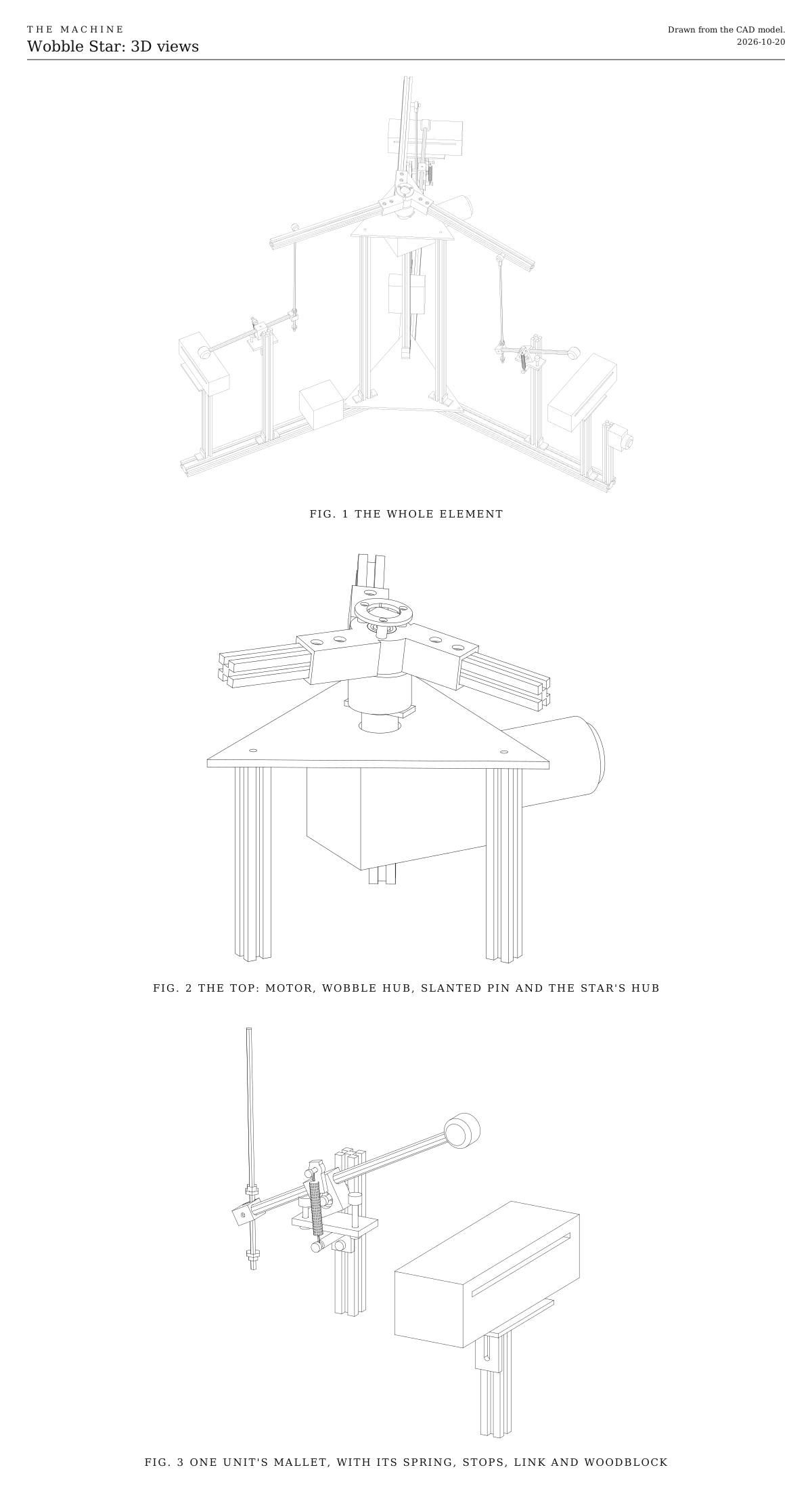
3D views. It shows the whole element from above and in front, the top of the tower with the motor, the wobble hub and the star's hub, and one unit's mallet up close, with its snap spring, its two rubber stops, its link and its woodblock. All three views are drawn from the CAD model.
Fig. 13D views. It shows the whole element from above and in front, the top of the tower with the motor, the wobble hub and the star's hub, and one unit's mallet up close, with its snap spring, its two rubber stops, its link and its woodblock. All three views are drawn from the CAD model.

How it works

  • Three identical units stand round a short tower, each on its own leg a third of a turn apart. Each is a mallet on a post over a woodblock. On top of the tower, a three-armed star wobbles, and a link hangs from each arm down to its unit’s mallet. We started with three woodblocks and hard rubber mallets; the choices below cover the alternatives.
  • The star wobbles without turning. A 12 V wiper motor hangs under the tower’s top plate with its shaft pointing up. A printed hub on its shaft holds an 8 mm pin at a slant of 7 degrees, and the star’s hub turns on that pin in two bearings. As the shaft turns, the pin sweeps a cone, and the star tilts toward each arm in turn, its high point going round once a turn, the way a coin wobbles as it settles. Each arm’s tip rises and falls about 9 cm.
  • The links keep it from turning. Each link runs through a slot in its mallet’s tail clip, which holds it sideways. Between them, the three slots stop the star from turning with the motor, so it only tilts.
  • Each mallet snaps. A spring from an anchor below each pivot to a horn on the mallet’s hub crosses the pivot at a tipping point, so the mallet rests either cocked up or down. As an arm rises, its link’s lower nut nudges its mallet past the point, and the spring throws the head down. As the arm comes back down, the upper nut nudges it back up, cocked. It’s the same snap mallet as on the See-Saw Beam.
  • The heads strike and spring back. A rubber stop under each shaft catches the snap with the head 2 to 3 mm above its block. The shaft flexes on, so the head strikes the wood and springs straight back off it, leaving the block free to ring.
  • So the strikes go round. The three arms rise in turn, so the three mallets strike in turn, evenly spaced, three to a turn: low, middle, high, again and again.
  • It plays crisply. Heads meet their blocks at about 1.7 m/s, a firm knock about as hard as a hand stroke, and every strike is about as hard at any tempo.
  • Three across the beat. At 120 beats a minute the motor turns 40 times a minute, one strike on every beat and three beats to a turn, so the figure starts a beat later in every bar of four. Turning once every two beats makes three against two; once a bar, three against four. The motor turns from about 20 to 70 times a minute.
  • It locks to the beat by starting and stopping. It can rest anywhere in its turn. Told to come in, the ESP32 starts the motor a moment early, so the first strike lands on the beat. An angle sensor on top of the star’s hub faces a magnet on the pin’s top end; the pin turns with the motor and the star doesn’t, so the sensor reads the motor’s turn at every moment, and the ESP32 nudges the motor’s speed to keep every strike on the beat. To stop, it stops the motor, and the motor’s worm gear holds the star where it is.
  • An ESP32-S3 runs it. It listens for the wireless signal, reads the sensor and sets the motor’s speed through a driver board, and it runs from the shared power-tool battery. If it hears nothing for a couple of seconds, it stops.

Ways to play

  • Play the rising figure, low, middle, high, one strike on every beat, against music in four.
  • Play three against two by turning once every two beats, or three against four by turning once a bar.
  • Change the figure between pieces by moving the lower nuts. Bunch two strikes together, or spread them unevenly for a lilt.
  • Swap the woodblocks round, and the figure falls instead of rising.

Before any code, run the motor slowly and watch the wave go round the star.

Notes

  • This is a first design. Expect one round of fitting when it’s built, most of it in setting the stops and the nuts.
  • The motion in the 3D model is simulated: the motor’s turn, the star’s wobble, and every mallet under gravity and its spring, between its stops and its link’s nuts. The model shows each shaft stopping on its stop; the last few millimeters of the head’s travel, as the shaft flexes, are too small to see. The springs, how much the stops bounce, how far the shafts flex and how fast the motor starts are guesses that a test build will measure.
  • Costs in the parts list are rough estimates for budgeting, not checked prices. They add up the version we started with.

References

  • Wobble plates and swashplates turn a spinning shaft into a wave of up-and-down motion round a circle. They drive the pistons of axial pumps and tilt the blades of a helicopter’s rotor.
  • A coin spun on a table, or the toy called Euler’s disk, wobbles the same way as it settles, its high point racing round faster and faster.
  • A light switch and a mousetrap both snap on an over-center spring, which is what each mallet does. A clock’s striking train lifts its hammer and lets it go onto the bell, stopping it just short with a check spring so the bell rings.

Parts

Ingredients

KindPartQtySourceEachFile
PrintedStar hub, turns on two bearings on the slanted pin and holds the three arms1··STL
PrintedSensor cap, holds the angle sensor over the pin's top end1··STL
PrintedWobble hub, bolts to the motor's crank arm and holds the pin at a slant1··STL
PrintedMallet hub, turns on two bearings, grips the mallet's shaft and carries the snap spring's horn3··STL
PrintedTail clip, grips the mallet's tail and carries its link3··STL
PrintedStop bar, holds the two rubber stops under each mallet's shaft3··STL
PrintedWoodblock cradle, an open frame that holds a woodblock on felt on top of its stand3··STL
FabricatedAluminum plate, 6 mm, cut into two trianglesThe base plate is a triangle about 31 cm on a side, and the top plate about 26 cm. Each is drilled for screws over its legs or uprights, and the top plate for the motor's shaft and mounting holes. A sign shop or a metal supplier can cut them, or use 12 mm plywood.1·$20.00
BoughtAluminum extrusion, 20 x 40 mm V-slot, 550 mm, for the legs3·$11.00
BoughtAluminum extrusion, 20 x 20 mm V-slot, for the tower, the posts, the stands and the star, cut to five lengthsThree of 614 mm for the tower's uprights, three of 390 mm for the mallets' posts, three of 280 mm for the woodblocks' stands, three of 350 mm for the star's arms, and one of 210 mm for the stop button's post. That's about 5.2 m in all.1·$16.00
BoughtCorner brackets for 20 mm V-slot, with screws and T-nutsTwo hold each mallet's post, one each woodblock's stand, two each of the tower's uprights, and one the stop button's post. The uprights' brackets bolt through the base plate into T-nuts in the legs below.16·$1.00
BoughtWiper motor, 12 V, with its crank armYour choice: see The driveAny car's wiper motor will do, or a universal one sold for props and robots, which usually comes with its arm. About 40 rpm on its slow terminal and 60 on its fast one, at 12 V.1·$35.00
BoughtMotor driver board, BTS7960 (often sold as IBT-2)It's the usual board for wiper motors, good for far more current than this one draws. It runs from the battery and takes its speed from the ESP32.1·$8.00
BoughtBall bearings, 608 size (8 mm bore, 22 mm across)Both go in the star's hub.2·$1.00
BoughtBall bearings, 625 size (5 mm bore, 16 mm across, 5 mm wide)Two in each mallet hub.6·$0.80
BoughtSteel dowel pin, 8 mm, 55 mm longThe slanted pin the star turns on.1·$1.00
BoughtShim washer, 8 mm bore, 1 mm thickOn the pin, between the wobble hub and the star's lower bearing.1·$0.50
BoughtRod ends for M5 (ball joints with a female thread)One at the top of each link.3·$2.00
BoughtM5 threaded rod, 1 mCut into three links, each about 40 cm.2·$3.00
BoughtM5 spherical washer pairs, and thick rubber washersA spherical pair goes under each upper nut, so it seats squarely on the tail clip however far the tail tips. A rubber washer goes on each lower nut, which softens its click and forgives a millimeter or two in setting it.3·$1.00
BoughtExtension springs, about 45 mm long between the hooks, about 1.2 N per mmYour choice: see How the heads strikeOne snaps each mallet. Stretched to 70 mm at the tipping point, it pulls about 30 N. A stiffer spring strikes harder, and needs more of the motor to cock it.3·$1.00
BoughtRubber feet with an M5 thread, about 12 mm acrossYour choice: see How the heads strikeThe stops, two under each mallet's shaft, on M5 x 30 screws with a nut, so each screws up or down to set where it catches the shaft.6·$0.50
BoughtXylophone mallets, hard rubber heads, about 28 mm, on 9.5 mm shaftsYour choice: see The mallet headsSold in pairs, so the fourth is a spare. Each shaft is cut to about 28 cm.4·$8.00
BoughtWoodblocks, three sizes, about 16 to 21 cm longYour choice: see What the mallets strikeThe biggest goes on the low unit, the leg that points to the right as you face it, and the smallest on the high unit.3·$15.00
BoughtSelf-adhesive felt, 3 mm, a small sheetFor the cradles, two strips under each block.1·$5.00
BoughtMagnetic angle sensor board, AS5600, with its magnetYour choice: see Choosing which mallets playThe small round magnet sold with it is magnetized across its face, which the sensor needs.1·$3.00
BoughtESP32-S3 development board1·$6.00
BoughtBattery adapter for the shared power-tool platform, and a 5 V buck converterThe motor runs from the battery, through the fuse, the stop button, the relay and the driver board. The ESP32 takes 5 V.1·$15.00
BoughtThe listener parts every element carries, as on the Control pageThey're a blade fuse holder and a 10 A fuse, a latching stop button with a spare contact and contacts rated 10 A, the status light, the number switches and their resistors. The stop switch under Choices has a plain two-pole switch in place of the stop button.1Link$12.00
BoughtMomentary push button, normally open, for the test buttonA short press plays each note once, and a long press relearns what the element can by itself. Any small panel button that closes while it's pressed will do.1·$1.00
BoughtRelay module, 5 V, high-level trigger, contacts rated 10 AIt's the switch the motor's power goes through, after the stop button. The driver board then sets the motor's speed.1·$2.00
BoughtTwo 10 kΩ resistors and two 4.7 kΩ resistorsThe 10 kΩ pair hold the relay and the driver off while the ESP32 starts. The 4.7 kΩ pair are for the sensor's long wires.1·$0.50
BoughtSmall project box, for the electronicsYour choice: see The electronics1·$5.00
BoughtM5 screws, T-nuts, spacers and nuts, assortedThe base plate and the uprights' brackets (nine M5 x 16 through the plate into the legs), the top plate (three M5 x 12 into the uprights' tapped ends), the star's arms (six M5 x 10 down through the hub), the three mallet pivots (M5 x 50, a 16 mm spacer, two washers), the three springs' anchors (M5 x 55 and a 40 mm spacer), the stop bars' second screws (three M5 x 12), the three links' rod ends (M5 x 25 and a 12 mm spacer each), the wobble hub (two M5 x 16 and nuts), and about twelve M5 nuts for the rods. Add three M4 x 20 screws and nuts for the springs' pins.1·$8.00
BoughtM3 screws, set screws, and nine M3 heat-set insertsThe set screws hold the mallet hubs and the tail clips on their shafts. The screws hold the sensor cap and the sensor's board.1·$4.00
Total$295.80

Tools

  • 3D printer, PETG
  • Hex keys, 1.5, 2, 2.5, 3 and 4 mm
  • Two 8 mm spanners, for the nuts on the rods
  • Soldering iron, for the heat-set inserts and the wiring
  • A drill with 5 and 6 mm bits, and a step bit or hole saw for the motor's shaft
  • A hacksaw, for the mallets' shafts, the threaded rod and the motor's arm
  • Pliers, or a loop of string, to stretch the springs on
  • A multimeter, to set the 5 V converter and find the motor's terminals

Choices

Decisions that are yours to make. Where we started is the version in the 3D model and the ingredients: a starting point, not the right answer.

How many legs

How many units stand round the tower?

ThreeWhere we started

SoundThree evenly spaced strikes a turn, going round. Against music in four, they fall across the beat, three against two or three against four, a built-in polyrhythm.

The fewest units to build, and the star is three arms on one hub. Every unit is the same, turned a third of the way round.

Four, an X

SoundFour strikes a turn, going round, so it plays straight beats, like a clock ticking round its face

One more unit, and the star becomes an X. Each arm's link moves the same, so the rest of the build is unchanged.

Five or more

SoundA ring of five or more notes going round, like a music box. Five woodblocks tuned to a pentatonic scale make a melody that never ends wrong.

A bigger star and a wider base, and each unit needs room round the tower. The tilt and the links stay the same.

Whatever the number, the strikes are evenly spaced by the star's symmetry. Only the lower nuts' settings move them earlier or later.

What the mallets strike

What sits under each head? There are three, and each can have its own voice.

Three woodblocksWhere we started

SoundA dry, clock-like knock in three pitches. Going round, they play a rising three-note figure, low, middle, high, again and again.

They're bought, about $10 to $20 each, and loud and clear under a snapped head. Each head springs straight back off its block, so it rings as long as the wood lets it.

Three tuned bars

SoundA rolling arpeggio of a chord, ringing, like a slow music box

Use xylophone bars or steel plates on felt rails, held at their nodes, about a quarter of the way in from each end. The snap suits them, because each head springs off the bar and leaves it ringing.

Three drums

SoundRounder and warmer, three pitches of thump going round

Small hand drums or practice pads, each held level on its stand under its head, in place of the cradles.

Found things

SoundEach has its own voice. A biscuit tin rattles, a flowerpot clunks and a pan lid rings.

They're free and the most surprising. Anything with a top that sits steady in a cradle will do.

Swap the blocks round and the figure falls instead of rising. The motor always turns the same way, so the order round the circle is the order you hear.

The mallet heads

What does each head strike with?

Hard rubberWhere we started

SoundA clear knock with a round edge to it, the classic woodblock sound

They're sold as xylophone mallets, in pairs, with 9.5 mm birch or rattan shafts. Hard rubber barely wears.

Yarn

SoundSoft and warm, more thud than knock

Yarn heads are light, and soften even a snapped strike. They suit tuned bars better than woodblocks.

Hard plastic or wood

SoundThe brightest and loudest, with a sharp click at the start

Acrylic or wooden heads mark soft wood over time. Try one on a single unit, for an accent each turn.

Felt

SoundThe softest, nearly a tap

Felt packs down over months. It's best where the element plays quietly under others.

How the heads strike

What throws each head onto its block, while the star keeps wobbling?

A snap springWhere we started

SoundA crisp, firm knock, about as hard as a hand stroke, and every strike is as hard as the last at any tempo. A quieter tick comes as each mallet flips back up.

A spring from below each pivot to a horn on the hub crosses the pivot at a tipping point, so the mallet rests either up or down. The link's lower nut nudges it past the point and the spring throws it down. A rubber stop catches the shaft with the head just above the block, and the shaft's flex carries the head on, so it strikes and springs straight back off. Heads land at about 1.7 m/s. It's the same snap mallet as on the See-Saw Beam.

A plain fall

SoundA gentle knock, about a third as hard, that grows with the tempo

There's no spring. A nut lifts the tail and lets the head follow it down onto the block, where it lies until it's lifted again, which shortens the ring. It's the simplest, but the head can only come down as fast as the arm lets it.

A lift and trip

SoundAs crisp as the snap spring, with no flip-up tick

A hook on each link lifts the tail against a spring, and a fixed ramp knocks it off near the top, as a clock's striking train does. It needs a hook, a ramp and fine setting for every mallet.

Something has to give. The motor always takes the star through its full wobble, so a link that drove a landed head on into its block would stall the motor or break a part.

What wobbles on top

What carries the links round the top of the tower?

A three-armed starWhere we started

SoundThe arms' tips rise and fall about 9 cm, in a slow wave going round

Three V-slot arms in a printed hub. It's light, and each link hangs from a T-nut in its arm's slot, so it slides out or in to change how far its mallet's tail moves.

A ball with three arms

SoundThe same strikes, under a slowly rolling planet

A bought ball, such as a hardwood ball or a hollow steel float, around the hub, with the same three arms through it. It's the most striking to look at, but heavier, and fixing the arms into it is harder.

A flat triangle plate

SoundThe same strikes

A triangle of aluminum or plywood with a link at each corner. It's the simplest to make, but it reads less like a mechanism.

The drive

Where does the motor sit?

On top, its shaft upWhere we started

SoundThe motor's groan comes from the top of the tower, right under the star

The wiper motor hangs under the tower's top plate, and the slanted hub goes straight onto its own crank arm, so there's no belt, crank or connecting rod. The angle sensor on the star reads the motor's turn directly.

At the foot, with a shaft up the tower

SoundThe groan stays low, in among the legs

The weight stays low and the motor is easier to reach, but a shaft has to run up the middle of the tower in two more bearings, with a coupling to the motor.

A smaller 24 V gearmotor

SoundQuieter, a hum instead of a groan

A fist-sized worm gearmotor, about 40 rpm at 24 V, runs straight from the battery with no limit on its speed signal. It's cheaper and quieter but far weaker, which matters here, since the motor cocks three springs a turn.

Choosing which mallets play

Do all three play on every turn, or can the beat choose?

All three, alwaysWhere we started

SoundThe same figure every turn, set by hand with the three lower nuts

It's the simplest. It comes in on the beat by starting the motor a moment early, and stops by stopping it. It can't turn without striking, so it can't line up in silence.

A damper on each block

SoundAny of the three can play or be hushed to a soft thud on any turn

A small servo beside each block swings a felt pad over its top, so a head snaps onto felt instead of wood. The mechanism runs on unchanged, so nothing can jam, and the star can wobble nearly silently while it lines up with the beat. It adds three servos and their wiring.

Free running

SoundA steady figure at its own tempo, drifting against the rest of the Machine

There's no angle sensor, just a speed setting. It's the least to build, but it never locks to the shared beat.

The stop switch

What cuts the motor's power at the element?

Latching emergency-stop button, with a spare contactWhere we started

The red mushroom head anyone nearby knows to hit. It stays down until it's twisted to release, so the element can't start again by accident. Its main contact cuts the power and its spare contact tells the ESP32. About $8.

Two-pole power switch, a rocker or a toggle

Smaller, plainer and cheaper, about $2. One pole cuts the power and the other tells the ESP32, so it does the same job. It doesn't read as a stop to someone who doesn't know the Machine, and it switches back on as easily as off. Rate its contacts above what the element draws, as the button's are.

Keep the second pole either way. It tells the ESP32 the power was cut, so it resets itself when the power comes back, as after a stop from the Bridge. Either way the relay stays, since it's how a stop from the Bridge reaches the element when no one is at it. A two-pole switch wires as the button does: one pole in place of the main contact, from 11 to 12, and the other in place of the spare contact, from 13 to 14.

Print

Material
PETG
Layers
0.2 mm
Walls
4
Infill
40%

Every part fits a 150 mm bed and prints without supports. PETG takes the knocks of the heads and the warmth of the motor better than PLA, but PLA is fine for a first try.

The printed parts

  • Star hub, turns on two bearings on the slanted pin and holds the three arms

    Which way up
    Flat, as it sits, with the arms' sockets running across the bed
    Supports
    None
    Time
    About 3 hours

    Both 608 bearings press in, one from the top and one from the bottom. Each socket's roof bridges over the arm. Three heat-set inserts go into its top, for the sensor cap.

    STL ↓
  • Sensor cap, holds the angle sensor over the pin's top end

    Which way up
    Upside down, its ring on the bed and its three legs standing up
    Supports
    None
    Time
    About 10 minutes
    STL ↓
  • Wobble hub, bolts to the motor's crank arm and holds the pin at a slant

    Which way up
    Flat on its bottom, the face that goes on the arm, with the slanted face up
    Supports
    None
    Time
    About 1 hour 30 minutes

    The 8 mm pin is a press fit in its slanted socket. The six-sided recess underneath fits over the nut that holds the arm on the motor, which centers the hub. Nuts for the two M5 screws drop into pockets inside.

    STL ↓
  • Mallet hub, turns on two bearings, grips the mallet's shaft and carries the snap spring's horn× 3

    Which way up
    Flat on its back, with the horn on top
    Supports
    None
    Time
    About 30 minutes each

    The three are the same, because every unit is the same turned round. The two 625 bearings press in, one from each face. A heat-set insert goes into the hole in its top, for the set screw onto the shaft. An M4 screw through the horn, with a nut behind, is the spring's pin.

    STL ↓
  • Tail clip, grips the mallet's tail and carries its link× 3

    Which way up
    Flat on one face, with the shaft's hole running across the bed
    Supports
    None
    Time
    About 10 minutes each

    A heat-set insert goes into the hole in its front face, for the set screw onto the shaft. The link runs through the slot behind the shaft, which also holds it sideways. Together, the three slots keep the star from turning with the motor.

    STL ↓
  • Stop bar, holds the two rubber stops under each mallet's shaft× 3

    Which way up
    On its back, the tab flat on the bed and the arm standing up
    Supports
    None
    Time
    About 30 minutes each

    Its tab bolts to the post below the pivot, held by the spring's anchor screw and one more.

    STL ↓
  • Woodblock cradle, an open frame that holds a woodblock on felt on top of its stand× 3

    Which way up
    Upside down, its top on the bed and the tab standing up
    Supports
    None
    Time
    About 50 minutes each

    One cradle fits every block. The block rests on felt along the frame's two long sides, and the open middle lets it ring. A rubber band round the block and the frame holds it if it walks.

    STL ↓

Assembly

  1. 1

    Lay the three legs on the floor a third of a turn apart, their inner ends 7 cm from the middle, and bolt the base plate across them, with screws into T-nuts in each leg's top slots.

    CheckThe legs are evenly spaced, and the base doesn't rock on a flat floor.

  2. 2

    Stand an upright on the base plate over each leg, 11 cm out from the middle, with a corner bracket on each side. Each bracket's screw goes through the plate into a T-nut in the leg below.

    CheckThe three uprights are square to the base and their tops are level.

  3. 3

    Find the motor's terminals with a multimeter. Drill the top plate's middle for the motor's shaft and its mounting holes, and bolt the motor under the plate, its shaft pointing up through it and its can pointing out between two uprights. Bolt the top plate onto the uprights' tapped ends.

    TrickyWiper motors have four or five terminals. One is the ground, often marked 31, and it's joined to the motor's case. The slow and fast windings are often marked 53 and 53b, and the other two are a switch that closes once a turn, which this build leaves unconnected. Touch the battery's − to the case and its + to each terminal in turn, briefly, to see which is which.

  4. 4

    Saw the motor's crank arm down to about 30 mm each side of its nut, and drill two 5 mm holes through it, 30 mm apart, centered on the nut. Press the pin into the wobble hub's slanted socket, then bolt the hub to the arm.

    TrickyThe hub has to sit centered on the motor's shaft. Its six-sided recess fits over the arm's nut, which centers it; if your arm's nut is a different size, enlarge the recess until it fits snugly. Press the pin fully home, or the star rides high and its hub can rub.

    CheckRun slowly, the pin's top end traces a small, even circle, and the hub doesn't wobble on the arm.

  5. 5

    Press the two bearings into the star's hub and melt the three inserts into its top. Drop two T-nuts into each arm's top slot and one into its front slot, for the link, and slide the arms into the hub's sockets, screwing each down. Slip the shim onto the pin and lower the star's hub over it.

    CheckThe star sits level on the hub, its hub clear of the wobble hub below by about 2 mm all round.

  6. 6

    Glue the sensor's round magnet onto the pin's top end, centered. Screw the board to the sensor cap, chip facing down, and the cap onto the star's hub.

    TrickyOff center by more than about a millimeter, the reading wobbles. An ordinary disc magnet won't work; it has to be the kind magnetized across its face, as sold with the board.

    CheckThe chip sits 1 to 2 mm above the magnet, square to it and centered on the pin.

  7. 7

    Cut the mallets' shafts to about 28 cm. Press two 625 bearings into each mallet hub and melt in its insert, and put an M4 screw through its horn with a nut behind, for the spring's pin. Slide a hub onto each shaft so the head's middle is 16 cm from the hub's middle, with the horn facing you, pointing up and a little toward the head when the shaft is level. Tighten the set screw. Then slide a tail clip onto the other end, 9 cm from the hub, the slot toward the post.

  8. 8

    Stand a post on each leg, 39 cm out from the middle, on the back half of the leg as you look out along it from the middle, with a corner bracket on each side. Bolt a stop bar to the front of each post, its arm 2.4 cm below where the pivot will be. The spring's anchor, an M5 screw on a 40 mm spacer, goes through its tab into a T-nut 4 cm below the pivot, and a second screw below that. Screw two rubber feet onto M5 screws in the arm, with a nut under it.

  9. 9

    Hang each mallet on its post with an M5 screw through the hub, a spacer and a T-nut in the post's front slot, 3 cm below the post's top, the head pointing out along the leg. Hook a spring from the horn's pin down to the anchor screw.

    TrickyThe spring pulls about 30 N. Stretch it on with pliers, or a loop of string, with the mallet resting on a stop, and keep fingers clear of the shaft as it flips.

    CheckPushed past its tipping point either way, with the horn straight up, the mallet flips over and stays where it lands, on one of its two stops.

  10. 10

    Stick a strip of felt along each long side of each cradle's frame, and bolt a cradle to the front of each stand. Stand the stands on the front half of each leg, under where each head lands, 55 cm out from the middle. Set a woodblock in each cradle, the biggest on the low unit.

  11. 11

    Hold each head on its woodblock and slide its cradle up or down the stand until the mallet's shaft is a little below level, about 5 degrees. Then screw the head-side stop up until it holds the head 2 to 3 mm above the block, and the tail-side stop until the cocked mallet's head sits about 9 cm above it.

    TrickyThe head-side stop sets the sound. Too low, and the head rests on the block and deadens it; too high, and the shaft can't flex far enough for the head to reach it. A stiffer shaft wants a smaller gap.

    CheckFlicked down by hand, the head strikes the block and springs straight back off it to rest just above it.

  12. 12

    Make the three links. Screw a rod end onto each length of threaded rod, then hang it from a screw and 12 mm spacer in its arm's front slot, 30 cm out from the middle, straight above its tail clip, and drop the rod down through the clip's slot. Thread on the upper nut and the spherical washers above the clip, and the rubber washer and the lower nut below it.

  13. 13

    Run the motor very slowly, with a test program and a hand on the stop button. Set each lower nut so it tips its mallet down just after its arm passes the middle of its rise, and each upper nut so it tips its mallet back up near the bottom of its arm's fall. As drawn, the lower nut sits about 6 cm below the upper.

    TrickyThe motor's gearbox won't turn backward, so the star can't be turned by hand; set the nuts with the motor crawling, or stopped between short runs. After each snap, the link must not catch the clip again before its arm turns back, or it drives the mallet into its stop and the motor stalls. Check each one through a full turn.

    CheckThrough each whole turn, every mallet snaps down once and flips up once, and no nut is ever still pushing a mallet that's already on its stop.

  14. 14

    Wire it in the box on the outside of the tower, following the wire list under Wiring. The fuse comes first, then the 5 V converter for the ESP32, and the stop button and the relay for the motor's power. The motor goes through the driver board, and the sensor to the ESP32 by four thin wires down an upright. Join all the grounds.

    TrickySet the 5 V converter with a multimeter before the ESP32 is connected. Most come set higher, and more than about 6 V destroys the board. Leave the sensor's wires a loose loop where they leave the star, so the wobble never pulls on them.

    CheckWith the battery in and no code running, the ESP32's light is on, the motor is still, and the star doesn't move. Press the stop button, release it, and nothing moves.

  15. 15

    Before playing, check what the ESP32 relies on. Run the motor slowly, with a hand on the stop button, and watch the angle the sensor reports. Then bring it to 40 turns a minute.

    CheckThe angle climbs smoothly all the way round, with no jumps, once a turn. At 40 turns a minute, the three mallets strike in turn half a second apart.

Wiring

The fuse comes first, right after the battery. The ESP32-S3 runs from the 5 V converter. The motor's power goes through the stop button and then the relay, so either one cuts it, and the driver board sets the motor's speed. The status light, the number switches and the battery reading are wired the same way on every element, so they're on the Control page, not here.

Wiring · Wobble Star
PowerSignalMotorGround, all joinedPins drawn faint are left empty.

Wire list

  1. Battery adapter, +

    Fuse, 10 A, in

    PowerRed, 14 AWG

    Keep it as short as the adapter allows. Nothing connects ahead of the fuse.

  2. Fuse, 10 A, out

    5 V converter, IN+

    PowerRed, 22 AWG

  3. Fuse, 10 A, out

    Stop button, 11

    PowerRed, 16 AWG

  4. Stop button, 12

    Relay module, COM

    PowerRed, 16 AWG

    The stop button's main contact opens when pressed, cutting the motor's power itself, so a program that hangs can't ignore it.

  5. Relay module, NO

    Driver board, BTS7960, B+

    PowerRed, 16 AWG

  6. 5 V converter, OUT+

    ESP32-S3 board, 5V

    PowerRed, 22 AWG

    Connect it only once the converter is set to 5 V.

  7. 5 V converter, OUT+

    Relay module, VCC

    PowerRed, 22 AWG

  8. ESP32-S3 board, 3V3

    Driver board, BTS7960, VCC

    PowerRed, 22 AWG

    The board's logic runs at the ESP32's 3.3 V, so its inputs match the ESP32's pins.

  9. ESP32-S3 board, 3V3

    Angle sensor (AS5600), VCC

    PowerRed, 24 AWG

    The sensor runs at 3.3 V so its signals match the ESP32's.

  10. ESP32-S3 board, 3V3

    Resistor, 4.7 kΩ, 1

    PowerThe resistor's own leg

  11. ESP32-S3 board, 3V3

    Resistor, 4.7 kΩ, 1

    PowerThe resistor's own leg

  12. Battery adapter, −

    5 V converter, IN−

    GroundBlack, 22 AWG

  13. Battery adapter, −

    Driver board, BTS7960, B−

    GroundBlack, 16 AWG

    This is the motor's return.

  14. 5 V converter, OUT−

    ESP32-S3 board, GND

    GroundBlack, 22 AWG

  15. Relay module, GND

    ESP32-S3 board, GND

    GroundBlack, 22 AWG

  16. Driver board, BTS7960, GND

    ESP32-S3 board, GND

    GroundBlack, 22 AWG

  17. Driver board, BTS7960, LPWM

    ESP32-S3 board, GND

    GroundA short jumper to the board's own GND pin

    Held low, the board can only run the motor one way, which keeps the motor's case, and the frame it's bolted to, at ground.

  18. Resistor, 10 kΩ, 2

    ESP32-S3 board, GND

    GroundThe resistor's own leg

  19. Resistor, 10 kΩ, 2

    ESP32-S3 board, GND

    GroundThe resistor's own leg

  20. Stop button, 14

    ESP32-S3 board, GND

    GroundBlack, 22 AWG

  21. Test button, 2

    ESP32-S3 board, GND

    GroundBlack, 22 AWG

  22. Angle sensor (AS5600), GND

    ESP32-S3 board, GND

    GroundBlack, 24 AWG

  23. Angle sensor (AS5600), DIR

    ESP32-S3 board, GND

    GroundA short jumper to the board's own GND pin

    It sets which way the angle counts. Left loose, the reading can flip.

  24. ESP32-S3 board, GPIO 5

    Relay module, IN

    SignalAny color, 22 AWG

  25. Resistor, 10 kΩ, 1

    Relay module, IN

    SignalThe resistor's own leg

    It holds the relay off while the ESP32 starts, when its pins float.

  26. ESP32-S3 board, GPIO 16

    Driver board, BTS7960, R_EN

    SignalAny color, 22 AWG

  27. ESP32-S3 board, GPIO 16

    Driver board, BTS7960, L_EN

    SignalAny color, 22 AWG

    Both halves of the board are switched on together.

  28. Resistor, 10 kΩ, 1

    Driver board, BTS7960, R_EN

    SignalThe resistor's own leg

    It holds the driver off while the ESP32 starts.

  29. ESP32-S3 board, GPIO 21

    Driver board, BTS7960, RPWM

    SignalAny color, 22 AWG

    The motor's speed, as a fast on-off signal. The firmware keeps it to about 65 percent of the time on, so the motor never sees more than about 12 V on average.

  30. ESP32-S3 board, GPIO 17

    Angle sensor (AS5600), SDA

    SignalAny color, 24 AWG

    The sensor's four wires leave the star in a loose loop and run down an upright, about 80 cm. Keep them together, twisted if you can.

  31. Resistor, 4.7 kΩ, 2

    ESP32-S3 board, GPIO 17

    SignalThe resistor's own leg

    The two 4.7 kΩ resistors keep the sensor's signals crisp over the long run. If the board has its own, these do no harm.

  32. ESP32-S3 board, GPIO 18

    Angle sensor (AS5600), SCL

    SignalAny color, 24 AWG

  33. Resistor, 4.7 kΩ, 2

    ESP32-S3 board, GPIO 18

    SignalThe resistor's own leg

  34. Stop button, 13

    ESP32-S3 board, GPIO 4

    SignalAny color, 22 AWG

    This is the stop button's spare contact, so the ESP32 knows it's been pressed.

  35. Test button, 1

    ESP32-S3 board, GPIO 14

    SignalAny color, 22 AWG

    The test button. The ESP32's own pull-up holds the pin high until it's pressed, so nothing else goes on this pin.

  36. Driver board, BTS7960, M+

    Wiper motor, 53

    MotorRed, 16 AWG

    The motor's slow winding, about 40 turns a minute at 12 V, which is one strike a beat at 120 beats a minute. The fast one, often marked 53b, suits faster tempos.

  37. Driver board, BTS7960, M−

    Wiper motor, 31

    MotorBlack, 16 AWG

    The ground terminal, which is joined to the motor's case.

Get these right

Set the converter first
Most 5 V converters come set higher. Turn its screw with the battery in and a multimeter on its output until it reads 5.0 V, and only then connect the ESP32. More than about 6 V destroys the board.
Keep the motor to about 12 V
The battery gives 18 to 20 V, and the motor is made for 12. The driver board switches the full battery on and off thousands of times a second, and the firmware never lets it be on more than about 65 percent of the time, so the motor sees about 12 V on average. Running it near full on for long overheats it.
A bigger fuse than most elements
The motor draws a few amps as it runs and much more for an instant as it starts. Use a 10 A fuse, and a stop button and relay with contacts rated 10 A. The firmware starts the motor gently, over a quarter of a second, which keeps that first draw down.
The motor's case is ground
Inside a wiper motor the ground terminal is joined to its case, and the case is bolted to the frame. Wire that terminal to the driver's M− and keep LPWM tied low, so it always stays at ground. Run backward, the whole frame would sit at the battery's voltage, and anything touching it and ground would short.
The stop holds the star
When the stop button cuts the power, the motor's worm gear stops the star where it is and holds it. Each mallet stays as it was, cocked or down on its stops.
The pins
Any free ESP32-S3 pins will do, except 0, 3, 45 and 46, which the board reads as it starts, 19 and 20, which are its USB port, and 35 to 37 on boards with eight megabytes of extra memory (marked R8). Pins 1 and 4 to 15 go to the parts every element shares, as on the Control page, the test button on 14 among them. If you use others, change them at the top of the firmware.

Mounting

Everything fixes to the V-slot frame with T-nuts and screws, so any part can slide to a new place or come off with a hex key. The three units are the same, each turned a third of the way round, with its post on the back half of its leg and its mallet in front of the post.

The base
The three legs lie on the floor, and the base plate bolts across their inner ends with screws into T-nuts in their top slots.
The tower
Each upright stands on the base plate over a leg, with a corner bracket on each side whose screw runs through the plate into the leg. The top plate screws into the uprights' tapped ends.
The motor
It hangs under the top plate on its own mounting holes, its shaft up through the plate's middle and its can pointing out between two uprights.
The star
The star's hub sits on the slanted pin on the motor's shaft. Each arm is held in its socket by two screws into T-nuts in its top slot, and its link hangs from a T-nut in its front slot, so it slides out or in along the arm.
The units
Each mallet turns on an M5 screw through a spacer into a T-nut in its post's front slot, 3 cm below the top, so the whole mallet slides up or down its post. Its stop bar and its spring's anchor are on the same post just below. Each woodblock's stand is a short upright on the front half of the leg, under where its head lands, and the cradle's slotted tab slides up or down it.
The angle sensor
It's on the sensor cap on top of the star's hub, held by two M3 screws. Its wires leave the star in a loose loop and run down an upright to the box.
The electronics
The box goes on the outside of one upright, about 15 cm up, on two T-nuts.
The stop button
It's in its own housing on a short post at the outer end of the low unit's leg, facing out, where a hand finds it without reaching past anything that moves.
The battery
The adapter sits on the high unit's leg just outside the base plate, so the pack slides on and off without moving anything else.
The wires
Clip-in slot covers hold the wires inside the extrusion's slots. The stop button's wires run along its leg's slot to the tower.

The electronics

Hidden in a box, or on show?

Closed boxWhere we started

A small project box, bought or printed, bolts to the outside of an upright. It's tidy and safe, but it hides the electronics.

Open plate

The boards sit on standoffs on a flat plate on an upright, with the wires dressed along the slot. The electronics become part of the look. It wants neat wiring, and nothing guards it.

Inside the tower

The boards ride on a plate between the uprights, under the motor, so the tower hides them without a box. They're harder to reach, and the motor's warmth is right above them.

Whichever you pick, keep the stop button on the outside, where anyone can reach it.

Tuning

Tuning

The test button
A short press turns the star once, so each mallet strikes once. Hold it for two seconds and it measures its strikes again, as it should after a nut moves. It works only while the element is resting, with no Bridge in range or with the Bridge holding it silent. While it plays or is stopped, the button does nothing. A stop ends a test at once, and pressing again ends one early.
Strikes too quiet
Use stiffer springs, or hang each anchor a little lower so its spring stretches further. Heavier heads, or hard plastic ones, sound louder at the same speed. Check the head-side stops too; a gap of 2 to 3 mm lets the head reach the block with most of its speed.
A dull, short knock
The head is resting on the block after it strikes, which deadens it. Raise the head-side stop a little, so the shaft stops the head just above the block.
A head snaps but never reaches its block
The gap is too big for the shaft to flex across, or the shaft is too stiff. Lower the head-side stop a little.
A mallet never snaps down
Its lower nut is too far down its rod to tip it past the tipping point. Run the nut up the rod, or slide the link a little further out along its arm, where the arm rises and falls further.
Strikes unevenly spaced
The star spaces the arms evenly, so an uneven figure comes from the nuts. Match the three lower nuts' distances below their eyes, or keep one a little different on purpose; it gives the figure a lilt.
The star creeps round
The three links, held sideways in their clips' slots, are what keep the star from turning with the motor. If it creeps, a slot has worn wide or a link has come loose; reprint the clip or tighten the link's rod end.
The motor slows or stalls
A nut is still pushing a mallet that's already on its stop. Move that nut away from the clip a little, and check each link hangs straight above its clip.
A tick each time a mallet cocks
That's the mallet flipping up onto its tail-side stop, a quiet second voice between the strikes. A softer rubber foot quiets it.
Strikes landing early or late
The firmware plans each strike from where the motor is in its turn, and how long after each arm passes the middle of its rise its mallet strikes. Moving a nut changes that, so let it measure the strikes again after any change.

Variations

A ring of five
Five units on five legs, a star of five arms, and five woodblocks tuned to a pentatonic scale make a melody going round that never sounds wrong, like a music box with no end.
Two stars, one over the other
A second, smaller star on the same pin, a little above the first, with its own three units on shorter posts between the legs. Offset by a sixth of a turn, it plays its three notes between the first star's, six to a turn.
A taller tower
A tower about 1.2 m tall, with longer links and the units higher up, puts the wobble at eye height. It strikes as hard, since the springs do the striking.
Turned by hand
Leave out the motor and the electronics, and put the wobble hub on a short shaft with a crank handle on top, so someone in the audience plays it. The tempo is theirs, and so is the figure's lilt.