Skip to content

The Machine · Recipes

Gravity Rod Machine

Design stage

Updated 2026-10-20

Identical steel rods stand in a column. Each cue pushes one in at the bottom, so the top one rolls off and falls onto a lever that throws a mallet up into a drum. The rod rolls home under the column to go round again.

Loading the model

Drag to turn · scroll to zoom

Printed

3DWhere we started. One version of it: 20 steel rods in the column, a 40 cm fall onto a lever, a felt mallet and a 10 inch frame drum. Press Play: the cams push a rod in at the bottom, the top one rolls off and falls, the lever throws the mallet into the drum, and the rod rolls home under the column. The motion is computed from the physics. Printed parts are drawn in orange; everything else is bought or cut from stock.

Overview

Cost, roughly
About $400
Printing
About 20 hours, over several prints
Building
Two weekends
Difficulty
Involved

Anatomy

1
Energy source
A rod falling from the top of the column
2
Control
A stepper turns two cams once, pushing a rod in at the bottom so the top one rolls off, about 0.9 s before the beat
3
Sounding body
A drum hung head-down over the mallet; we started with a 10 inch frame drum
4
Reset
The rod rolls back under the column and waits to be pushed in again
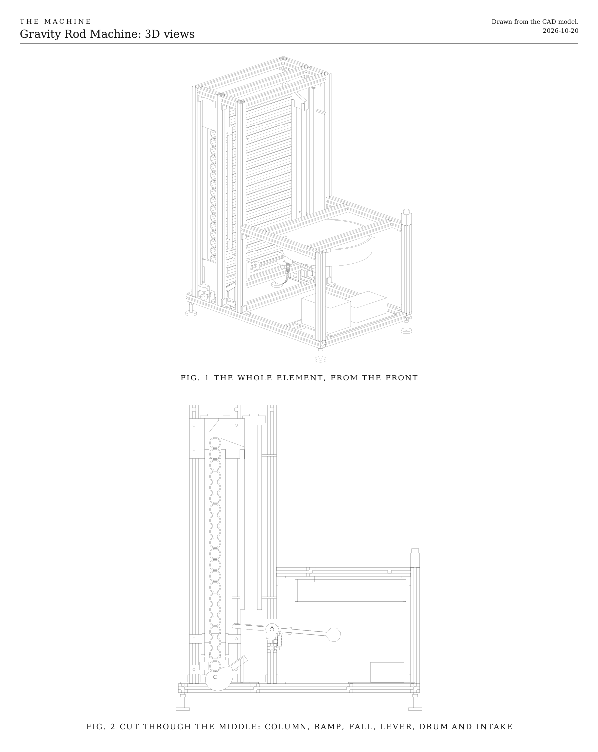
3D views. The whole element from the front, and cut through the middle, where the rods' path makes a loop. Drawn from the CAD model.
Fig. 13D views. The whole element from the front, and cut through the middle, where the rods' path makes a loop. Drawn from the CAD model.

How it works

  • Identical steel rods stand in a tall column, their ends running between guide bars at each side. Spring catches near the bottom hold the column up, and the next rod waits under it, on two cams.
  • On cue, a stepper turns the cams once. They push the waiting rod up past the catches, and the whole column rises by one rod.
  • At the top, the column’s front wall stops short. The top rod rises past this lip, and the leaning back wall nudges it forward, over the lip and down a short ramp into a chute in front of the column.
  • It falls freely down the chute, 40 cm in 0.29 s, the same every time.
  • Partway down it lands on the long arm of a lever. The lever’s short arm carries a felt mallet, which flies up into a frame drum hung head-down above it. The springy handle lets the head bounce off, so the drum rings.
  • The tipped arm rolls the rod off onto two felt-lined rails, which slope back under the column. The rod rolls in onto the cams and waits to be pushed in again. A spring sets the lever back.
  • One motor does the release and the return, and nothing carries the rods back up. Each push at the bottom is what lifts every rod a step closer to the top.
  • Only the mallet should sound. The rods wear heat-shrink sleeves, and everything they land on or roll along is lined with felt or rubber.
  • Every strike is planned ahead. From the cams starting to the mallet hitting takes about 0.9 s, so the element starts the cams that much before the beat. Control announces single hits about a second ahead and rhythms further ahead, so the time is there, but not much to spare.
  • It plays a medium stroke, with the mallet leaving at about 2.7 m/s. A longer fall or heavier rods hit harder, so the fall is the volume knob.
  • An ESP32 listens for the broadcast signal and drives the cams’ stepper. A slot sensor tells it where the cams are, and a switch behind the waiting rod tells it a rod is ready. It runs from the shared battery, and the stop button cuts the motor’s power.
  • The model and the files are one version, where we started: 20 rods of 3/4 inch conduit in the column, a 40 cm fall, a felt mallet and a 10 inch frame drum. The rods, the fall, the mallet, the target and how the top rod leaves are yours to choose, under Parts.

Ways to play

  • It can strike once on cue: one rod and one hit, about 0.9 s after the cue.
  • With only the one rod waiting, it can strike about once every 1.4 s, while that rod comes home. Lay a few spare rods on the rails and it can play rhythms with hits as close as about 0.4 s, for as long as the spares last.
  • The column is part of the show. It creeps up one rod with every hit, and the audience sees each rod roll off the top and drop before they hear it.

The top wheel

The wheel is a choice for the look, and for a release that comes at the same moment every time. The cams still lift the column. Only what happens at the top changes, and the model doesn’t draw it, so these notes stand in for its parts.

  • A wheel with two pockets turning half a turn can’t do it. Its pocket faces down to take the rod rising from the column, so half a turn later it would face up over the chute and couldn’t let go. With four pockets and a quarter turn, the pocket that took the rod at the bottom ends up facing down and forward over the chute, and the rod falls out.
  • Make two wheels, one at each end of the rods like the cams, about 20 cm across and 8 mm thick. Each has four half-circle pockets 26 mm across, with their middles about 85 mm from the shaft. Lock both to one 8 mm shaft with their pockets exactly in line.
  • The shaft runs across directly above the column, in two pillow blocks on the top rails, high enough that the bottom pocket sits just over the column’s top. The frame grows about 13 cm taller to carry it.
  • A guard of bent sheet or a printed strip curves round the front of the wheels, from the bottom to above the chute. It keeps the rod in its pocket until the pocket is over the chute.
  • The column heads lose their lip and ramp. Both walls of the slot end just below the wheel, and the chute’s bars reach up under the wheel’s front. The rod now falls from higher, so move the lever up by as much to keep the 40 cm fall, or keep the longer fall for a harder hit.
  • To keep one motor, put a 20-tooth GT2 pulley on the cam shaft’s left end and an 80-tooth on the wheel’s shaft, joined by a closed belt about 1.4 m long outside the left side frame. Or give the wheel its own stepper and TMC2209, wired like the cams’ driver from the same relay, so its timing can be set in the program instead.
  • Set the timing with the cams at their low point. A pocket sits at the bottom, centered over the column, around the top rod. The next pocket has to reach the bottom just as the cams finish lifting, about five sixths of the way through their turn. With the belt, that’s set by which tooth the belt goes on, so test it by hand, turning the cams slowly.
  • The rod lets go about three quarters of the way through the quarter turn, so the strike lands about 0.6 s after the cue.

Notes

  • This is a first design, drawn and not built. Expect a round of fitting.
  • The motion in the model is computed from simple physics: the cams’ steady lift, rods rolling down the ramp, the arm and the rails, free fall, and the lever. The strike speed comes from sharing the falling rod’s momentum with the lever. A test build will give the real figures.
  • Costs in the parts list are rough estimates for budgeting, not checked prices. They add up the version we started with.
  • There’s no program for this element in the downloads. The Gantry Pendulum’s firmware has the shared listening code to build on.

Parts

Ingredients

KindPartQtySourceEachFile
PrintedColumn foot, left, holds the spring catches and the guide bars' lower ends1··STL
PrintedColumn foot, right, the mirror of the left1··STL
PrintedColumn head, left, with the lip, the ramp and the leaning back wallYour choice: see How the top rod leaves1··STL
PrintedColumn head, right, the mirror of the leftYour choice: see How the top rod leaves1··STL
PrintedCam, lifts the waiting rod and the column above it over most of a turn2··STL
PrintedLever hub, holds the mallet's handle and lands on the bumpers1··STL
PrintedCatch arm, the rod lands on a pair of these2··STL
FabricatedIntake rails, two strips of aluminum angle, felt-lined, on short postsThey run from under the lever's tip down to the column's foot, ending level with the cams' low point, outside the cams and inside the guide bars.1·$5.00
BoughtAluminum extrusion, 20 x 20 mm V-slot, for one side frame: a 543 mm base rail, uprights of 262 mm and three of 628 mm, a 303 mm drum rail, and top rails of 60 and 75 mm2·$26.00
BoughtAluminum extrusion, 20 x 20 mm V-slot, 314 mm, for the crossbars10·$3.00
BoughtCorner brackets for 20 mm V-slot, with screws and T-nuts50·$1.00
BoughtLeveling feet, M5 thread4·$2.00
BoughtSteel conduit, 3/4 inch EMT, 3 m, cut into 300 mm rods (25 in all, 20 for the column and a few to wait)Your choice: see The rods3·$8.00
BoughtHeat-shrink tubing, 1 inch, cut into 300 mm sleevesYour choice: see The rods1·$25.00
BoughtAluminum square tube, 10 x 10 mm, 3.5 m, cut into the guide bars (four of 435 mm for the column, two of 360 and two of 415 mm for the chute)1·$12.00
BoughtSpring plungers with a ball nose, M8, heavy, for the catchesTwo at each end of the column, one in front and one behind, holding up the bottom rod.4·$3.00
BoughtSmall L-brackets, to tie the chute's bars to the uprights8·$1.00
BoughtSteel rod, 8 mm, 750 mm, cut into two shafts (cams 397 mm, pivot 314 mm)File a flat wherever a grub screw bites.1·$6.00
BoughtPillow block bearings, KP08 (8 mm), for the cam shaft2·$3.00
BoughtFlange bearings, KFL08 (8 mm), for the lever's pivot2·$3.00
BoughtNEMA 17 stepper motor, 48 mm body1·$14.00
BoughtGT2 pulleys, 20 teeth for the motor and 60 teeth for the cam shaft, and a 232 mm closed GT2 belt, 6 mm wideThe 3:1 step-down gives the motor an easy job lifting the column.1·$10.00
BoughtNEMA 17 mounting plate, with short aluminum standoffs to the frame1·$6.00
BoughtTMC2209 stepper driverQuiet enough that the motor doesn't whine over the drum.1·$6.00
BoughtShaft collar, 8 mm, with a long M3 screw in its side as a flag, and an optical slot sensor (a 3D printer endstop)The sensor tells the ESP32 when the cams are at their low point.1·$4.00
BoughtFelt mallet, about 30 mm headYour choice: see The malletCut its handle so the middle of the head sits 140 mm from the pivot.1·$12.00
BoughtExtension spring, light, about 6 mm across and 30 mm long, with an M5 eye bolt1·$3.00
BoughtRubber bumpers, adhesive, and a rubber strip for the catch arms1·$5.00
BoughtFrame drum, 10 inchYour choice: see The target1·$25.00
BoughtSmall L-brackets with felt pads, to hold the drum by its rimYour choice: see The target4·$1.00
BoughtAdhesive felt sheet, for the rails, the ramp and the chute's stop1·$4.00
BoughtMicro switch with roller lever, behind the waiting rodPressed while a rod waits on the cams, so the ESP32 knows the next turn will release one.1·$2.00
BoughtESP32 development board1·$6.00
BoughtBattery adapter for the shared power-tool platform, and a 5 V buck converterThe stepper driver runs from the battery, through the fuse, the stop button and the relay. The ESP32 takes 5 V.1·$15.00
BoughtThe listener parts every element carries, as on the Control pageA blade fuse holder and 2 A fuse, a latching stop button with a spare contact, the status light, the number switches and their resistors. The stop switch under Choices has a plain two-pole switch in place of the stop button.1Link$12.00
BoughtMomentary push button, normally open, for the test buttonA short press plays each note once, and a long press relearns what the element can by itself. Any small panel button that closes while it's pressed will do.1·$1.00
BoughtRelay module, 5 V, high-level trigger, contacts rated 10 AThe switch the motor's power goes through.1·$2.00
BoughtElectrolytic capacitor, 100 µF, 35 VAcross the driver's motor supply, to soak up the spikes the motor sends back.1·$1.00
BoughtSmall project box, for the electronicsYour choice: see The electronics1·$5.00
BoughtPlywood or aluminum plate, about 250 x 150 mm, for the electronics and the battery1·$5.00
BoughtM5 screws, T-nuts and washers, assorted1·$8.00
BoughtM3 screws, nuts and grub screws, assorted1·$4.00
Total$398.00

Tools

  • 3D printer, PETG
  • Hex keys, 1.5, 2.5, 3 and 4 mm
  • Pipe cutter or hacksaw, and a file, for the rods
  • Heat gun, for the sleeves
  • An M8 tap, for the catches
  • Hacksaw and file, for the guide bars and the rails
  • Soldering iron
  • A multimeter, to set the 5 V converter
  • A phone that films in slow motion, to measure the timing

Choices

Decisions that are yours to make. Where we started is the version in the 3D model and the ingredients: a starting point, not the right answer.

The rods

What falls? Every rod in the loop is the same.

Steel tube, 3/4 inch EMT conduit, 300 mmWhere we started

SoundA medium stroke. From a 40 cm fall the mallet leaves at about 2.7 m/s.

About 0.2 kg each, cut from hardware-store conduit. Sleeve each one in heat-shrink so it rolls, stacks and lands quietly.

The same tube, filled with sand and capped

SoundA harder stroke from the same fall

About 0.1 kg heavier and the same size. The cams then lift about 7 kg each turn, so the motor and the catches work harder, and the caps have to stay on through thousands of drops.

Steel tube, 1 inch EMT

SoundA louder stroke, the mallet about a quarter faster

About 0.3 kg each. The wider rod needs the slot, the cams and the chute sized up to match, and the column gets heavier to lift.

Hardwood dowel, 25 mm

SoundA soft stroke, the quietest of these

About 0.1 kg each, so the column is light and easy to lift, and the lever wants a lighter spring. Quiet even without sleeves.

The cams lift every rod in the column on every turn, so the rods' weight is also the motor's load. Don't mix sizes or weights in one loop.

How far it falls

How far is the lever below the end of the ramp?

About 25 cm

SoundSofter, with the mallet at about 2.1 m/s

A quicker fall, about 0.23 s.

About 40 cmWhere we started

SoundA medium stroke, with the mallet at about 2.7 m/s

The fall takes 0.29 s.

About 60 cm

SoundLouder, with the mallet at about 3.3 m/s

The fall takes 0.35 s, and the column grows eight rods taller to lift the release, or the lever and the intake sink lower.

The fall is the volume knob. A rod's speed grows with the square root of the fall, so doubling it plays only about 40% harder.

The mallet

What strikes the drum?

FeltWhere we started

SoundA round, warm thump with a soft attack

A bass drum or timpani mallet. Gentle on the head.

Yarn or wool

SoundSofter still, more boom than attack

A marimba mallet. Light, so the fall does all the work.

Rubber

SoundPunchier, with a clear attack

A hard rubber xylophone or practice mallet. It brings out metal targets.

Wood

SoundA sharp, dry crack

A wooden ball on a handle. Hard on drum heads, and best on wood and metal.

Give it a springy handle, of rattan, bamboo or thin fiberglass rod. Then the head flies the last few millimeters on its own and bounces off. A stiff handle presses the head into the drum and chokes it.

The target

What does the mallet strike?

Frame drum, 10 inchWhere we started

SoundA deep, round thump that rings a little

Light and cheap, and it hangs easily by its rim.

Tom or snare

SoundA fuller drum sound, and a snare adds a buzz

Heavier. Hang it from its lugs, or with a bought tom clamp on a crossbar.

Wood block or cajón top

SoundA dry, sharp knock

Any dense, hollow piece of wood, clamped face down.

Metal

SoundA bright ring that carries, from a bell, a cowbell, a pot lid or a steel plate

Hang it from its rim or a cord so it can ring. Pinched flat, it only clanks.

The mallet swings up, so whatever it strikes hangs face down above it, from two crossbars. Set it where the mallet just reaches it at the end of its swing.

Where the lever sits

Where does the falling rod meet the lever?

Partway downWhere we started

SoundThe audience sees the whole fall, then the mallet flips up and the rod is tipped aside.

The lever's long arm both catches the rod and rolls it onto the intake, so one part does two jobs. Its catch arms, hub and stops are printed, and need tuning.

At the bottom, on a kick drum pedal

SoundA kick drum beater striking sideways, the classic bass drum sound if it hits a bass drum

Almost all bought. The rod lands on the footboard and rolls off it onto the intake, with the pedal mounted at a slant, and the pedal's own spring resets it. The fall can use more of the frame's height, so it can hit harder.

The column

How do the rods get back up to the top?

Tall, lifting itselfWhere we started

SoundQuiet between strikes. The whole column creeps up one rod with each hit, and you hear only a soft click from the catches.

One motor does the release and the return, with no chain. About 25 rods, and the cams lift all of them, about 4.5 kg, on every turn, so the catches and the motor have to be up to it.

Short, fed by a chain lift

SoundA soft chain rattle under the music

A chain lift with paddles carries each rod up to a short column mounted high, and the cams push it in at the bottom there. Fewer rods and a lighter push, but a second motor, two chains and a lot more parts.

How the top rod leaves

The cams lift the column either way. What takes the top rod off it?

It rolls over the lipWhere we started

SoundNothing moves at the top but the rod. It rises past the front lip, the leaning back wall nudges it over, and it rolls down a short ramp into the chute.

No extra parts, since the lip and the ramp are printed into the column heads, and the one motor does everything. The roll over the lip and down the ramp takes a little more or less time with each rod, so the lead time, about 0.9 s, wants checking now and then. A rod that hesitates on the lip makes a late hit.

A pocket wheel at the top

SoundA big wheel with four pockets turns a quarter turn over the column at every hit. The top rod rises into the pocket at its bottom, rides round the front and drops into the chute. The turning wheel is the show at the top.

The rod lets go at the same point of every turn, so the timing stays steady, and the lead time drops to about 0.6 s. It adds two printed wheels about 20 cm across, a shaft in two pillow blocks, a guard round the front, plain column heads without the ramp, and a taller frame. It can stay on one motor with a 4:1 belt from the cam shaft, since the cams turn once per hit and the wheel a quarter turn, or take its own small stepper and driver. Setting the wheel so a pocket is waiting just as the top rod rises into it is the tricky part.

The 3D model and the files show the lip. The Overview's notes under "The top wheel" say how to build the wheel.

The stop switch

What cuts the motor's power at the element?

Latching emergency-stop button, with a spare contactWhere we started

The red mushroom head anyone nearby knows to hit. It stays down until it's twisted to release, so the element can't start again by accident. Its main contact cuts the power and its spare contact tells the ESP32. About $8.

Two-pole power switch, a rocker or a toggle

Smaller, plainer and cheaper, about $2. One pole cuts the power and the other tells the ESP32, so it does the same job. It doesn't read as a stop to someone who doesn't know the Machine, and it switches back on as easily as off. Rate its contacts above what the element draws, as the button's are.

Keep the second pole either way. The ESP32 knows where the cams are only by counting the steps it sends, so the second pole is how it learns the power was cut, and finds the slot sensor's mark again before it moves. Without it, cams turned by hand while it was off could let a rod go off its beat. Either way the relay stays, since it's how a stop from the Bridge reaches the element when no one is at it. A two-pole switch wires as the button does: one pole in place of the main contact, from 11 to 12, and the other in place of the spare contact, from 13 to 14.

Print

Material
PETG
Layers
0.2 mm
Walls
4
Infill
30%

Every part fits a 150 x 130 mm bed. Nothing needs supports. PETG takes the knock of a falling rod and the column's weight better than PLA.

The printed parts

  • Column foot, left, holds the spring catches and the guide bars' lower ends

    Which way up
    Flat on its backing plate, walls up
    Supports
    None
    Time
    About 3 hours

    Tap the two catch holes M8 once it's printed, or melt in M8 threaded inserts.

    STL ↓
  • Column foot, right, the mirror of the left

    Which way up
    Flat on its backing plate, walls up
    Supports
    None
    Time
    About 3 hours
    STL ↓
  • Column head, left, with the lip, the ramp and the leaning back wall

    Which way up
    Flat on its backing plate, walls up
    Supports
    None
    Time
    About 4½ hours

    The ramp's top is what the rods' ends roll on. Print it smooth, or sand it.

    STL ↓
  • Column head, right, the mirror of the left

    Which way up
    Flat on its backing plate, walls up
    Supports
    None
    Time
    About 4½ hours
    STL ↓
  • Cam, lifts the waiting rod and the column above it over most of a turn× 2

    Which way up
    Flat, hub up
    Supports
    None
    Time
    About 1½ hours each

    Print both from the one file. An M3 nut and grub screw lock each one to a flat on the shaft.

    STL ↓
  • Lever hub, holds the mallet's handle and lands on the bumpers

    Which way up
    On its side, as the file lies, with the shaft hole upright
    Supports
    None
    Time
    About 1½ hours
    STL ↓
  • Catch arm, the rod lands on a pair of these× 2

    Which way up
    On its side, as the file lies
    Supports
    None
    Time
    About 45 minutes each

    Print both from the one file.

    STL ↓

Assembly

  1. 1

    Cut your rods to 300 mm, all the same. File the ends smooth, slide a sleeve over each and shrink it with the heat gun.

    TrickyThey have to match. A long rod binds in the column's slot, and a short one wanders sideways on the lever. Cut one, then use it as the gauge for the rest.

    CheckEvery rod is within a millimeter of the others, and each rolls straight across a table.

  2. 2

    Build the two side frames flat on the floor, from the base rail, the four uprights, the drum rail and the two short top rails, with two corner brackets at every joint. The CAD script has every length and where it sits.

    CheckLaid one on the other, the two side frames match.

  3. 3

    Stand the side frames up and join them with the ten crossbars, at the heights in the model. Fit a leveling foot under each end of both base rails.

    TrickyThe crossbars set the gap between the side frames, 314 mm inside, and the column needs it right to a millimeter or two. Measure it top and bottom before you tighten.

    CheckThe frame stands square and doesn't rock. Pushed sideways at the top, it doesn't sway.

  4. 4

    Bolt the two column feet low and the two column heads high on the inside faces of the column uprights. Push the four column guide bars into their sockets between them, then the chute's four bars, tying them to the uprights with the small brackets.

    TrickyThe slot has to be straight and the same width from top to bottom. A bar a millimeter out of line makes the column bind as it rises.

    CheckA rod dropped in at the top slides all the way down the column's slot without catching. One dropped into the chute falls straight through.

  5. 5

    Screw the four spring catches into the feet from outside, so their balls stand 2 to 3 mm into the slot.

    TrickyThe catches hold the whole column, about 4.5 kg. Too soft and the column sags between hits; too hard and the cams struggle to push past them. Start in the middle of their range.

    CheckPushed up from below by hand, a rod clicks past the balls, and let go, it sits on them.

  6. 6

    File two flats on the cam shaft, in line. Slide it through the pillow blocks on the base rails with the two cams on it, and lock the cams with their low points together, straight under the slot.

    TrickyThe cams have to match exactly, or one end of the column rises before the other and it jams.

    CheckTurned by hand, both cams rise under the slot together, and fall away together.

  7. 7

    Fit the 60-tooth pulley on the cam shaft outside the right side frame, the stepper on its plate above it with the 20-tooth pulley, and the belt between them. Fit the collar with its flag screw on the left end, and the slot sensor where the flag sits in it with the cams at their low point.

    CheckTurned by hand, the shaft turns freely, and the sensor's light changes once a turn, as the cams come to their low point.

  8. 8

    File flats on the pivot shaft. Bolt the two flange bearings to the inside of the lever uprights. Slide the shaft through them with the hub in the middle and a catch arm near each end, and lock them with grub screws, both arms pointing back under the chute at the same angle.

    CheckRocked by hand, the lever swings freely through its range.

  9. 9

    Stick a strip of rubber along the top of each catch arm. Bolt the stop bar between the lever uprights below the pivot, and stick the two bumpers on it, where the hub's two feet land at each end of the swing.

    CheckAt rest, the front foot sits on its bumper with the arms tipped up a little. Pushed down, the back foot lands on the other bumper, with the arms sloping down toward the column.

  10. 10

    Push your mallet's handle into the hub and pin or glue it, with the middle of the head about 140 mm from the pivot. Hook the spring between the hub's tab and an eye bolt in the stop bar's front face.

    TrickyThe spring pulls against the strike. Too strong and it robs the hit and can throw a rod off the arm. Too weak and the lever is still on its way back when the next rod lands. Start light and add tension until it returns cleanly.

    CheckPushed to its stop and let go, the lever springs back to rest in a fraction of a second, without bouncing.

  11. 11

    Hang your target face down from the two drum crossbars with the four padded clips. Set its height so that, with the lever held on its stop, the mallet head sits 3 to 5 mm below it.

    TrickyThat gap is what lets the mallet bounce. Too close and the head is still pressed against the drum when it lands, which chokes it to a thud. Too far and the springy handle can't reach.

    CheckFlick the lever down by hand. The mallet hits, bounces off, and the drum rings on.

  12. 12

    Cut the two intake rails from aluminum angle, line their tops with felt, and stand them on their posts so they slope down from under the catch arms' tips and end level with the cams' low point, just in front of the slot. Bolt the roller switch to the inside of the right column foot, behind where a rod waits.

    CheckA rod set on the tips of the catch arms rolls off, lands on the rails, and rolls in under the column onto the cams, against the feet's back walls, pressing the switch.

  13. 13

    Load the column. Drop rods into the slot from the top until it's full up to the lip, about 20, then lay one on the cams and the rest on the rails.

    TrickyThe top rod has to roll forward, not back. The head's leaning back wall only touches it once it's clear of the lip. If it hesitates at the top, sand a little off the lean; if it jams against the lip, the cams aren't lifting far enough.

    CheckTurned slowly by hand, each turn of the cams lifts the whole column by one rod, and the top one rolls forward over the lip, down the ramp and into the chute.

  14. 14

    Wire it on the plate at the front, following the wire list under Wiring. The fuse comes first, then the 5 V converter for the ESP32, and the stop button and the relay for the driver's power. Join all the grounds.

    TrickySet the 5 V converter with a multimeter before the ESP32 is connected. Most come set higher, and more than about 6 V destroys the board.

    CheckWith the battery in and no program running, the motor turns freely by hand and the ESP32's light is on. Press the stop button, release it, and nothing moves.

  15. 15

    Load a program that listens for Control. On each hit it turns the cams one full turn, starting the measured lead time before the beat, if the entry switch says a rod is waiting. The Gantry Pendulum's firmware has the listening code to start from.

    TrickyMeasure the lead time rather than trusting the model. Film the cams and the drum together in slow motion and count the frames from the cams starting to the mallet hitting. The model says about 0.93 s.

    CheckOn cue, one rod drops and the mallet strikes, and a moment later it rolls home onto the cams.

Wiring

The fuse comes first, right after the battery. The ESP32 runs from the 5 V converter. The motor's power goes through the stop button and then the relay, so either one cuts it. The status light, the number switches and the battery reading are wired the same way on every element, so they're on the Control page, not here.

Wiring · Gravity Rod Machine
PowerSignalMotorGround, all joinedPins drawn faint are left empty.

Wire list

  1. Battery adapter, +

    Fuse, 2 A, in

    PowerRed, 16 AWG

    As short as the adapter allows. Nothing connects ahead of the fuse.

  2. Fuse, 2 A, out

    5 V converter, IN+

    PowerRed, 22 AWG

  3. Fuse, 2 A, out

    Stop button, 11

    PowerRed, 18 AWG

  4. Stop button, 12

    Relay module, COM

    PowerRed, 18 AWG

    The stop button's main contact opens when pressed, cutting the motor's power itself, so a program that hangs can't ignore it.

  5. Relay module, NO

    TMC2209 driver, VM

    PowerRed, 18 AWG

  6. Capacitor, 100 µF, +

    TMC2209 driver, VM

    PowerThe capacitor's own leg

    Solder its legs straight onto the driver's VM and GND pins. The stripe on its side marks the − leg.

  7. 5 V converter, OUT+

    ESP32 board, 5V

    PowerRed, 22 AWG

    Only once the converter is set to 5 V.

  8. 5 V converter, OUT+

    Relay module, VCC

    PowerRed, 22 AWG

  9. ESP32 board, 3V3

    TMC2209 driver, VDD

    PowerRed, 22 AWG

    The driver's logic runs at the ESP32's 3.3 V, so its signals match.

  10. ESP32 board, 3V3

    Slot sensor, VCC

    PowerRed, 22 AWG

    3.3 V, not 5 V, so the sensor's signal can't rise above what the pin takes.

  11. Battery adapter, −

    5 V converter, IN−

    GroundBlack, 22 AWG

  12. Battery adapter, −

    TMC2209 driver, GND

    GroundBlack, 18 AWG

    The motor's return. Use the driver's GND pin next to VM.

  13. Capacitor, 100 µF, −

    TMC2209 driver, GND

    GroundThe capacitor's own leg

  14. 5 V converter, OUT−

    ESP32 board, GND

    GroundBlack, 22 AWG

  15. ESP32 board, GND

    TMC2209 driver, GND

    GroundBlack, 22 AWG

    The driver's other GND pin, next to VDD.

  16. Relay module, GND

    ESP32 board, GND

    GroundBlack, 22 AWG

  17. Resistor, 10 kΩ, 2

    ESP32 board, GND

    GroundThe resistor's own leg

  18. Entry switch, COM

    ESP32 board, GND

    GroundBlack, 22 AWG

  19. Slot sensor, GND

    ESP32 board, GND

    GroundBlack, 22 AWG

  20. Stop button, 14

    ESP32 board, GND

    GroundBlack, 22 AWG

  21. Test button, 2

    ESP32 board, GND

    GroundBlack, 22 AWG

  22. ESP32 board, GPIO 25

    TMC2209 driver, STEP

    SignalAny color, 22 AWG

  23. ESP32 board, GPIO 26

    TMC2209 driver, DIR

    SignalAny color, 22 AWG

  24. ESP32 board, GPIO 27

    TMC2209 driver, EN

    SignalAny color, 22 AWG

    Low turns the motor on. The ESP32 holds it high between hits, so the motor doesn't hum. At rest the column sits on the catches, not the cams, so nothing needs holding.

  25. ESP32 board, GPIO 33

    Relay module, IN

    SignalAny color, 22 AWG

  26. Resistor, 10 kΩ, 1

    Relay module, IN

    SignalThe resistor's own leg

    Holds the relay off while the ESP32 starts, when its pins float.

  27. Entry switch, NO

    ESP32 board, GPIO 32

    SignalAny color, 22 AWG

    The switch's normally open contact, which closes while a rod waits on the cams. A broken wire then reads as no rod waiting, so the element skips the hit rather than turning the cams for nothing.

  28. Slot sensor, OUT

    ESP32 board, GPIO 23

    SignalAny color, 22 AWG

    Changes as the flag passes, once a turn, so the ESP32 knows where the cams are.

  29. Stop button, 13

    ESP32 board, GPIO 13

    SignalAny color, 22 AWG

    The stop button's spare contact, so the ESP32 knows it's been pressed.

  30. Test button, 1

    ESP32 board, GPIO 15

    SignalAny color, 22 AWG

    The test button. The ESP32's own pull-up holds the pin high until it's pressed. The board reads GPIO 15 as it starts, but only to choose whether to print, so holding the button then does no harm.

  31. TMC2209 driver, 1A

    Cam stepper, A1

    MotorThe motor's own cable

    1A and 1B go to one coil, 2A and 2B to the other.

  32. TMC2209 driver, 1B

    Cam stepper, A2

    MotorThe motor's own cable

  33. TMC2209 driver, 2A

    Cam stepper, B1

    MotorThe motor's own cable

  34. TMC2209 driver, 2B

    Cam stepper, B2

    MotorThe motor's own cable

Get these right

Set the converter first
Most 5 V converters come set higher. Turn its screw with the battery in and a multimeter on its output until it reads 5.0 V, and only then connect the ESP32. More than about 6 V destroys the board.
Set the driver's current
The TMC2209 has a small screw that sets the motor's current. Start low and raise it until the motor turns the cams under a full column without skipping. If the motor is too hot to keep a hand on, it's set too high.
Finding the motor's coils
Motor wire colors vary by maker. Touch two wires together and turn the shaft by hand; if it suddenly turns stiffly, those two are one coil. If the motor runs backwards, swap the two wires of one coil.
Never unplug the motor with power on
Disconnecting a running stepper can destroy its driver. Press the stop button first.
The pins
Any free ESP32 pins will do, except 0, 2, 5 and 12, which the board reads as it starts, and 34 to 39, which have no pull-up for the switch. The board reads 15 as it starts too, but only to choose whether to print, so 15 carries the test button on every element. If you use others, the program needs to know.

Mounting

Everything fixes to the V-slot frame with T-nuts and screws, so any part can slide to a new place with a hex key. Both shafts run across between the side frames, and the motor sits outside them, clear of the rods.

The frame
Corner brackets, two at every joint, with M5 screws into T-nuts in the slots. A leveling foot sits under each end of both base rails, on a T-nut in the bottom slot.
The column
The two printed feet bolt low and the two printed heads bolt high on the inside faces of the column uprights, two M5 screws into each upright. The four guide bars sit in their sockets between them.
The chute
Its back bars hang from sockets under the heads' ramps, and its front bars stand in front. Small L-brackets tie them to the lever and column uprights.
The cam shaft and motor
The pillow blocks sit on top of the base rails, on T-nuts. The motor's plate stands off the outside of the two right column uprights, above the shaft, so the belt runs straight down to the shaft's pulley.
The slot sensor
On a small bracket on the left base rail, astride the flag on the collar.
The lever
Its two flange bearings bolt to the inside of the lever uprights, and the stop bar with its bumpers runs between those uprights below the pivot.
The drum
Four padded clips grip its rim and hang it from the two drum crossbars. The clips slide along the crossbars to fit any size of drum.
The intake rails
Each rail stands on two posts on a strip that rests on the crossbar in front of the cams. The entry switch bolts to the inside of the right column foot.
The electronics and the battery
On a plate across the two front crossbars of the base, under the drum, where the wires run short to the motor along the slots.
The stop button
In its own housing on top of the right front upright, the first thing a hand reaches.
The wires
Clip-in slot covers hold the wires inside the extrusion's slots, away from the rods and the lever.

The electronics

Hidden in a box, or on show?

Closed boxWhere we started

A small project box, bought or printed, on the plate. Tidy, and safe from a stray rod, but it hides the electronics.

Open plate

The boards on standoffs on the plate, with the wires dressed along the slots. The electronics become part of the look. It wants neat wiring, and nothing guards it.

DIN rail

A short length of 35 mm DIN rail on the plate, with each board in a snap-on holder. It looks like a control panel, and any board comes off with a flick. The holders add a few dollars.

Whichever you pick, keep the stop button on the outside, where anyone can reach it.

Tuning

Tuning

The test button
A short press drops one rod, about a second after you let go, if one is waiting. Hold it for two seconds and it turns the cams slowly to the slot sensor's mark. If they were part way round, that can let a rod go. It works only while the element is resting, with no Bridge in range or with the Bridge holding it silent. While it plays or is stopped, the button does nothing. A stop ends a test at once, and pressing again ends one early. The lead is still measured from slow-motion film.
A clank as the rod lands on the lever
The rod is landing on bare arm, or one end is landing first. Check the rubber strips, and that the ramp's two halves are level, so both ends roll off together.
A thud where the drum should ring
The mallet is staying on the head. Raise the drum a millimeter or two, or use a springier handle.
A double hit, a quick "ta-dak"
The handle is springing the head back into the drum, or the lever is bouncing off its stop. Try a stiffer handle, a softer bumper, or lower the drum a little.
Strikes too quiet
Let it fall farther, use heavier rods, or a harder mallet. A stronger spring makes it quieter, not louder.
Strikes landing early or late
The lead time is off. Film it in slow motion again and correct it. Check it again after a few hours of playing, as the rubber beds in and the catches wear.
The column binds or rises unevenly
A guide bar is out of line, or the cams don't match. Check the slot with a rod at a few heights, and line the cams up again. A little dry PTFE spray on the bars helps.
The column sags between hits
The catches are too soft for its weight. Screw them in a quarter turn at a time until it holds.
The top rod rolls back, or sits on the lip
It's being nudged before it clears the lip, or not at all. Sand the lean of the head's back wall, or check that the cams lift the column a little more than one rod.
A tap under the music as the column rises
The rods knock against each other or the bars as they move. That's the column working, and it's quiet; if it bothers you, a slower turn of the cams softens it.
Missed hits
No rod was waiting on the cams when the cue came. With one rod in the loop's return, it can strike only about once every 1.4 s. A few spare rods waiting on the rails let it play faster, up to about one hit every 0.4 s, which is as fast as the lever comes back.

Variations

Mallets along the fall
Several levers beside the fall, at different heights, each tapped by the falling rod as it passes, each with its own mallet and target. One drop then plays a short figure. A falling rod speeds up, so evenly spaced levers play a roll that quickens. For even beats, space them from the release in the ratio 1, 4, 9, which is 5, 20 and 44 cm for beats a tenth of a second apart. Each lever the rod brushes takes some of its speed, so the later beats come a little late and soft, and the spacing is found by testing.
A gate on the rails
When spare rods queue on the rails, the next one rests against the cams while they turn. A sprung finger on the rails, pressed down by the cams at their low point, would hold the queue back until there's room, and keep the cams from rubbing.
A light gate on the fall
An optical sensor across the chute, just above the lever, tells the ESP32 exactly when each rod passes. It can then correct its own lead time as the rubber wears, instead of waiting to be told.
Two columns, two drums
A wider frame with two columns side by side, each with its own cams, chute, lever and drum, one high and one low. They can share one motor through a clutch, or each have their own for call and answer.
Another size
A taller column lifts the release and lengthens the fall, so it hits harder, but the cams then lift more rods. Longer rods and a wider frame look heavier. The slot, the cams and the chute scale with the rods' diameter, and the frame's width with their length. Keep every rod in the loop the same.